Absolute and relative coordinates. Absolute and relative coordinate system
Coordinates that indicate the location of a point, given the screen's coordinate system, are called absolute coordinates. For example, PSET(100,120) - means that a dot will appear on the screen 100 pixels to the right and 120 pixels below the upper left corner, i.e. screen origin.
The coordinates of the point that was last drawn are stored in the computer's memory. This point is called the last reference point (TLP). For example, if you specify only the coordinates of one point when drawing a line, then a segment from the TPS to the specified point will be drawn on the screen, which after that will become the TPS itself. Immediately after turning on graphics mode, the last link point is the point in the center of the screen.
In addition to absolute coordinates, QBASIC also uses relative coordinates. These coordinates show the amount of movement of the TPS. To draw a new point using relative coordinates, you need to use the STEP(X,Y) keyword, where X and Y are the offset of the coordinates relative to the TPS.
For example, PSET STEP(-5,10) - in this case, a point will appear, the position of which will be 5 points to the left and 10 points lower relative to the last link point. That is, if the point of the last link had coordinates, for example, (100,100), then a point with coordinates (95,110) will be obtained.
Drawing lines and rectangles.
LINE(X1,Y1)-(X2,Y2),C- draws a segment connecting the points (X1, Y1) and (X2, Y2) with color C.
For example, LINE(5,5)-(10,20),4
Result: 5 10
If you do not specify the first coordinate, then a segment will be drawn from the TPS to a point with coordinates (X2, Y2).
LINE(X1,Y1)-(X2,Y2), C, B- draws a rectangle outline with diagonal ends at points (X1, Y1) and (X2, Y2), C - color, B - rectangle marker.
For example, LINE(5,5)-(20,20), 5, B
Result: 5 20

If you specify BF instead of marker B, then a filled rectangle (block) will be drawn:
LINE(X1,Y1)-(X2,Y2),C, BF
For example, LINE(5,5)-(20,20),5, BF
 Result: 5 20
Drawing circles, ellipses and arcs.
CIRCLE(X,Y), R, C- draws a circle centered at the point (X, Y), radius R, color C.
For example, CIRCLE(50,50), 10, 7
Result:
 50
50
CIRCLE(X,Y), R, C, f1, f2- an arc of a circle, f1 and f2 arc angle values in radians from 0 to 6.2831, defining the beginning and end of the arc.
CIRCLE(X,Y), R, C, e- ellipse, centered at the point (X, Y), radius R, e - the ratio of the vertical axis to the horizontal.
For example, CIRCLE(50,50), 20, 15, 7, 1/2
Result: 30 50 70

If necessary, after the C parameter, you can specify the values of the ellipse arc angles f1 and f2.
PAINT(X,Y), C, K- paint with color C the figure drawn with color K, (X, Y) - a point lying inside the figure. If the outline color matches the fill color, then only one color is indicated: PAINT(X,Y), C
For example, you need to paint the circle CIRCLE(150,50), 40, 5 with color 4. To do this, you need to execute the PAINT(150,50), 4, 5 statement, because the center of the circle lies exactly inside the shape being filled, we used it as an interior point.
Problem solving.
Task 1.
Draw four points that lie on the same horizontal line at a distance of 20 pixels from each other. The last link point has coordinate (15, 20).
Solution: NOTES.
SCREEN 9: COLOR 5.15:REM graphic mode, background 5, color 15
CLS:REM screen cleaning
PSET(15,20) :REM draws a point at coordinates (15,20)
PSET STEP(20,0) :REM draws a point with an offset
PSET STEP(20,0) :REM relative to last by 20
PSET STEP(20,0) :REM pixels on the x-axis.
Result: 15 35 55 75

20. . . .
Task 2.
Draw three circles whose centers lie on the same horizontal line at a distance of 30 pixels from each other. The radii of the circles are 20, the center of the first circle coincides with the center of the screen.
Solution.
 SCREEN 9 120 150 180
CIRCLE STEP(0, 0), 20, 15 100
CIRCLE STEP(30, 0), 20, 15
CIRCLE STEP(30, 0), 20, 15
Task 2.
Construct a quadrilateral with vertices (10.15), (30.25), (30.5) and (20.0).
LINE (10,15)-(30,25), 5
LINE - (30, 5),5
LINE - (25,0), 5
LINE - (10,15), 5
RESULT: 5 10 20 25 30
 15
15
Write a program to draw an arbitrary picture.
Helpful advice: Before you start writing a program, draw a picture on a piece of paper in a cage and arrange the desired coordinates. You will immediately see what numbers will be used as operands in your program.
CSS -P and second, it is only supported by Netscape browsers.And him programming in JavaScript, it's a minefield between the two major browsers. When viewing these pages, please be aware that each browser loads its own property description page. positioning and programming these properties.
Until the advent of CSS-P, the only means of relatively accurate positioning there were tables. They made it possible to accurately position the components of an HTML page relative to each other on a plane. CSS-P allows you to accurately place the markup element not only relative to other components of the page, but also relative to the page boundaries.
In addition, CSS-P adds another dimension to the page - markup elements can "run into" each other.
In this case, you can change the order of "collision" - shift the layers. To verify this, it is enough to use the link from the above example.
But that's not all.
Layers can be developed. (open)
Rice. 5.1.

Rice. 5.2.
The term "layer" instead of "block" markup element" is used here for the reason that it better reflects the effect that is achieved by positioning, and not at all to spite the supporters of Microsoft.
Now let's move on to the discussion of attributes. positioning. (open)

Rice. 5.3.

Rice. 5.4.
Coordinates and dimensions
The CSS-P standard allows for pixel-accurate placement of a block markup element in the working field of the browser window. With this approach, a natural question arises: how does the coordinate system work, in which the author of the page arranges the placement of its components.
CSS-P defines two coordinate systems: relative and absolute. This allows you to provide flexibility in the placement of elements both relative to the boundaries of the working field of the browser window, and relative to each other.
Blocks are not abstract points that do not take up space on the page plane. Blocks are rectangles that "sweep" an area. The text and other page components under the block become inaccessible to the user, so linear dimensions block are no less important for creating HTML pages than its coordinates .
Using " absolute" coordinates, the origin point is placed in the upper left corner of the parent box (for example, the browser window), and the X and Y axes are directed to the right horizontally and down vertically, respectively:

Rice. 5.5.
If, in this coordinate system, some block element should be placed 10 px below the top edge of the browser client area and 20 px to the right of the left edge of the browser client area, then its description will look like this:
Example ( position:absolute;top:10px; left:20px; )
In this entry, the coordinate system type is specified by the position attribute (value - absolute ), the X coordinate is specified by the left attribute (value - 20 px ), the Y coordinate is specified by the top attribute (value - 10 px ).
The top and left attributes define the coordinates of the block 's top left corner in absolute coordinates . (open)

Rice. 5.6.
Coordinate values can also be negative. To remove a block from the displayed area with linear dimensions 100 px (height) by 200 px (width) is enough position its like this: (open)
Example ( position:absolute; top:-100px;left:-200px; width:200px;height:100px; )

Rice. 5.7.
Absolute positioning is used when either the entire content of the page must be accessible without scrolling ("scrolling"), or when markup elements are at the beginning of the page and their relative position is important from a design point of view, for example, to use pop-up menus.
This coordinate system allows you to place blocks on the page in the coordinates of the block that encloses them. The advantages of such a coordinate system are obvious: it allows you to save the relative position of the markup elements at any size of the browser window and its default settings.
As a starting point in this coordinate system the placement point of the current block is selected by default. The X axis is directed horizontally to the right, and the Y axis is directed vertically down.
To set the coordinates of a block, this system uses a record like: (open)

Rice. 5.8.
To work with relative system coordinates, it is better to use universal DIV blocks. This is because in Netscape Navigator, for example, a paragraph cannot contain paragraphs. Any block immediately closes the paragraph, so you can't put anything inside it.
IN relative system
Let's take a direct logical path, without being distracted by many modern international and domestic scientific terms. The coordinate system can be depicted as a certain reference system oriented on the plane in two directions, and in space in three. If we recall the mathematical system, then it is represented by two mutually perpendicular directions, which have the names of the abscissa (X) and ordinate (Y) axes. They are oriented in the horizontal and vertical directions, respectively. The intersection of these lines is the origin with zero values in absolute value. And the location of points on the plane is determined using two coordinates X and Y. In geodesy, the orientation of the axes on the plane is different from mathematics. The planar rectangular system is defined by the X-axis in the vertical position (north direction) and the Y-axis in the horizontal position (east direction).
Classification of coordinate systems
Polar systems include geographic, astronomical and geodetic, geocentric and topocentric systems.
Geographic coordinate system
The closed surface of the outer contour of the Earth is represented by a spheroid geometric shape. Arcs on the surface of the ball can be taken as the main orientation directions on it. On a simplified representation of a reduced model of our planet in the form of a globe (the figure of the earth), you can visually see the accepted reference lines in the form of the Greenwich meridian and the equatorial line.
In this example, it is the spatial system of geographical coordinates that is generally accepted throughout the world. It introduces the concepts of longitude and latitude. Having degree units of measurement, they represent an angular value. Many are familiar with their definitions. It should be recalled that the geographic longitude of a particular point represents the angle between two planes passing through the zero (Greenwich) meridian and the meridian at the location being determined. Under the geographical latitude of a point, the angle formed between the plumb line (or normal) to it and the plane of the equator is taken.
The concepts of astronomical and geodetic coordinate systems and their differences
The geographic system conventionally combines the astronomical and geodetic systems. In order to understand what differences still exist, pay attention to the definitions of geodetic and astronomical coordinates (longitude, latitude, height). In the astronomical system, latitude is considered as the angle between the equatorial plane and the plumb line at the point of definition. And the very shape of the Earth in it is considered as a conditional geoid, mathematically approximately equated to a sphere. In the geodetic system, latitude is formed by the normal to the surface of the earth's ellipsoid at a particular point and by the plane of the equator. The third coordinates in these systems give the final idea of their differences. The astronomical (orthometric) height is the elevation along the plumb line between the actual height and a point on the surface of the level geoid. The geodesic height is the normal distance from the ellipsoid surface to the calculation point.
Gauss-Krüger Plane Rectangular Coordinate System
Each coordinate system has its own theoretical scientific and practical economic application, both globally and regionally. In some specific cases, it is possible to use reference, local and conditional coordinate systems, but which, through mathematical calculations and calculations, can still be combined with each other.
The geodetic rectangular planar coordinate system is a projection of the individual six-degree zones of the ellipsoid. By inscribing this figure inside a horizontally located cylinder, each zone is separately projected onto the inner cylindrical surface. The zones of such a spheroid are limited by meridians with a step of six degrees. When deployed on a plane, a projection is obtained, which is named after the German scientists who developed it Gauss-Kruger. In this way of projection, the angles between any directions retain their magnitudes. Therefore, sometimes it is also called equiangular. The abscissa axis in the zone passes through the center, through the conditional axial meridian (X axis), and the ordinate axis along the equator line (Y axis). The length of the lines along the axial meridian is transmitted without distortion, and along the equatorial line with distortion to the edges of the zone.
Polar coordinate system
In addition to the rectangular coordinate system described above, the presence and use of a plane polar coordinate system in solving geodetic problems should be noted. For the initial reference direction, it uses the axis of the northern (polar) direction, hence the name. To determine the location of points on the plane, the polar (directional) angle and the radius vector (horizontal distance) to the point are used. Recall that the directional angle is the angle measured from the original (northern) direction to the determined one. The radius vector is expressed in the definition of a horizontal distance. Geodetic measurements of vertical angle and slope distance are added to the spatial polar system to determine the 3D position of points. This method is used almost daily in trigonometric leveling, topographic surveys and for the development of geodetic networks.
Geocentric and topocentric coordinate systems
Satellite geocentric and topocentric coordinate systems are partially arranged according to the same polar method, with the only difference that the main axes of three-dimensional space (X, Y, Z) have different origins and directions. In the geocentric system, the origin of coordinates is the center of mass of the Earth. The X axis is directed along the Greenwich meridian towards the equator. The Y-axis is placed in a rectangular position to the east of X. The Z-axis initially has a polar direction along the minor axis of the ellipsoid. Its coordinates are:
- in the equatorial plane the geocentric right ascension of the satellite
- in the meridian plane the geocentric declination of the satellite
- geocentric radius vector is the distance from the Earth's center of gravity to the satellite.
When observing the movement of satellites from a point of standing on the earth's surface, a topocentric system is used, the coordinate axes of which are parallel to the axes of the geocentric system, and the observation point is considered to be its beginning. Coordinates in such a system:
- topocentric right ascension satellite
- topocentric satellite declination
- topocentric radius vector of the satellite
- geocentric radius vector at the observation point.
The modern satellite global reference systems WGS-84, PZ-90 include not only coordinates, but also other parameters and characteristics important for geodetic measurements, observations and navigation. These include geodesic and other constants:
- original geodetic dates
- earth ellipsoid data
- geoid model
- gravity field model
- values of the gravitational constant
- value of the speed of light and others.
So, using coordinates, in AutoCAD you can draw a line of any length and with any direction. Simply put, when we are faced with the task of creating a drawing, for example, such as shown in Fig. 2.2, we can, having made certain calculations, calculate the absolute coordinates of all vertices, and then, using the Segment command, create a drawing by entering these coordinates from the keyboard. Of course, this method of creating drawings cannot be called convenient, and therefore AutoCAD supports two systems of not absolute, but relative coordinates.
These systems are called relative because when creating the next object (for example, the same lines), not the origin of coordinates (0,0), but the previous point is used as a reference point. If, for example, the first point of the line has coordinates (100,150), and a line of length 200 units must be located to the right of this point strictly horizontally, the relative coordinates of the second point of the line will be (200.0) - 200 units in the positive direction of the x-axis and 0 units in the direction of the Y axis. The absolute coordinates of the same point will be equal to (300,150).
This principle is valid for the system of relative Cartesian coordinates, in which the position of a point is described by X and Y coordinates. In the system of relative polar coordinates, its position is described by the distance from the reference point and the angle measured from the horizontal direction. Most users use the relative Cartesian coordinate system more often, but this does not mean that the relative polar coordinate system can be ignored. Working in AutoCAD, sooner or later you may encounter a situation where creating an object without using a polar coordinate system will be much more difficult. We will look at examples of such situations in Chapter 4.
When entering relative coordinates, they must be preceded by a symbol @ . So, in the above example of drawing a line in relative coordinates, @200.0 would have been entered to create the second point.
Presence of a symbol @ tells AutoCAD that the numbers following it are coordinate values that should be measured from the previous point.
Relative Cartesian Coordinates
The system of Cartesian coordinates, known to us since school, was proposed in the 17th century by the French mathematician Rene Descartes. This system of describing the position of a point uses horizontal (X) and vertical (Y) coordinates, measured from the point (0,0). Relative Cartesian coordinates are no different from absolute ones, except that they are counted not from the origin, but from the previous point. Simply put, relative coordinates show how far from the selected point you should draw a line or move an object (Fig. 2.6). If the offset is left, the x-coordinate will be negative. Similarly, if the offset is downward, then the Y-coordinate will be negative. This system is useful if the horizontal and vertical distances from one point to another are known. Relative coordinates should be entered in the following format: @X,Y.
Rice. 2.6 Relative Cartesian coordinate system
Relative polar coordinates
In the system of relative polar coordinates, the distance between these points (polar radius) and the angle that specifies the direction (polar angle) are used to specify the position of the next point relative to the previous one. In this case, the polar radius is always considered as a positive value. As for the reference of the polar angle, AutoCAD has chosen the direction to the right as the zero reference axis (or, as they say, "three o'clock"), and the polar angle is counted counterclockwise (Fig. 2.7). Thus, the upward direction (“at twelve o’clock”) corresponds to an angle of 90 °, to the left (“at nine o’clock”) - an angle of 180 °, downward (“at six o’clock”) - 270 °, and a full turn - an angle of 360 ° .

Rice. 2.7 Relative polar coordinate system
When entering a polar angle, it should be indicated with a less than symbol (
Depending on the setting of dimensions on the drawing of the part, as well as on the basis of the convenience of programming and the capabilities of the CNC machine, the position of any element of the geometry of the part can be set in an absolute or relative coordinate system.
IN absolute coordinate system the reading is made from the initial zero point. Set by function G 90 (absolute) . If we consider the absolute coordinate system using the example of processing two holes 1 and 2 (Fig. 3.22, a), then it can be noted that the position of the middle of the first hole (point 1) will be determined by the dimensions X 1 and Y 1 from zero
(from the origin of the coordinate system), and the position of the second hole (point 2) will also be set from zero by the dimensions X 2 and Y 2.
 |
|
| A) | b) |
Rice. 3.22. Coordinate systems: a - absolute (absolute); b - relative (incremental)
IN relative coordinate system counting is made from the last point of a trajectory of movement. Set by function G 91 (incremental) . If we analyze the principle of specifying the coordinates of points in a relative reference system (Fig. 3.22, b), then it can be noted that the position of the first hole, similarly to the previous one, will be determined by the dimensions X 1 and Y 1 from zero (from the origin of the coordinate system), while the position of the second hole will be set from point 1 by the dimensions X 2 and Y 2. In other words, in a relative reference system, the coordinates of the next point are given in increments from the last given point.
Questions and tasks for self-control
1. What is a control program block?
2. What does the frame of the control program consist of?
3. Define the coordinate system.
4. What is a Cartesian coordinate system?
5. Define the polar coordinate system.
6. What is called a spherical coordinate system?
7. What is the difference between absolute and relative reference systems?
8. Define linear, circular, and helical interpolations.
9. Name the types and purpose of the information contained in the control program.
10. Describe the composition of the control program frame N 001 G 01 X-004000 T 02 L 02 F6 25 S 24 M 03 M 08 LF.
Tests for the section
1. Part of the control program, consisting of information for performing one transition when processing a part or for moving the support from one point to another when positioning (retraction, approach), as well as for executing technological commands, is called:
a) frame;
b) a word;
c) address;
d) coordinate system;
e) the content of the address.
2. The part of the frame containing information about one of the programmable functions (commands) is called:
a) a word
b) address;
c) coordinate system;
d) the content of the address.
3. Conditional naming of the programming language of devices with numerical control is:
A) G-code;
b) M-code;
V) S-code;
G) F-code;
e) C or C+.
4. The set of numbers that determine the position of any point is called:
a) point coordinates;
b) coordinate system;
c) radial coordinate;
d) the polar axis.
5. A set of definitions that implements the coordinate method, i.e. a way to determine the position of a point or body using numbers or other symbols is called:
a) coordinate system;
b) point coordinates;
c) radial coordinate;
d) the polar axis.
Tasks (exercises, situational tasks, etc.)
with sample implementations, solutions
 Absolute and relative coordinate system
 Mongol invasion on the territory of Kazakhstan
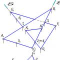 Construction of a line of intersection of planes defined in various ways