How to draw solid figures. The concept of a dimetric rectangular projection
In isometric projection, all coefficients are equal to each other:
k = t = n;
3 to 2 = 2,
k = yj 2UZ - 0.82.
Therefore, when constructing an isometric projection, the dimensions of the object, plotted along the axonometric axes, are multiplied by 0.82. Such recalculation of sizes is inconvenient. Therefore, for simplicity, an isometric projection is usually performed without reducing the size (distortion) along the axes x, y, i, those. take the reduced distortion coefficient equal to unity. The resulting image of the object in isometric projection is somewhat larger than in reality. The increase in this case is 22% (expressed as the number 1.22 = 1: 0.82).
Each segment directed along the axes x, y, z or parallel to them, retains its magnitude.
The location of the isometric projection axes is shown in fig. 6.4. On fig. 6.5 and 6.6 show orthogonal (a) and isometric (b) point projection BUT and segment L AT.
Hexagonal prism in isometry. The construction of a hexagonal prism according to this drawing in a system of orthogonal projections (on the left in Fig. 6.7) is shown in Fig. 6.7. On the isometric axis I put off height H, draw lines parallel to the axes hiu. Mark on a line parallel to the axis X, position of points / and 4.
To build a point 2 determine the coordinates of this point in the drawing - x 2 and at 2 and, setting aside these coordinates on the axonometric image, build a point 2. Points are built in the same way. 3, 5 and 6.
The constructed points of the upper base are connected to each other, an edge is drawn from the point / to the intersection with the x-axis, then -
dotted edges 2 , 3, 6. The ribs of the lower base are drawn parallel to the ribs of the upper one. Building a point L, located on the side face, along the coordinates x A(or at A) and 1 A evident from

Circle isometry. Circles in isometry are depicted as ellipses (Fig. 6.8) indicating the values of the axes of the ellipses for the reduced distortion coefficients equal to one.
The major axis of the ellipses is at 90° for ellipses lying IN THE PLANE xC>1 to OSI y, IN THE PLANE y01 TO X-AXIS, in plane hoy To OSI?

When constructing an isometric image by hand (like a drawing), an ellipse is performed at eight points. For example, trays 1, 2, 3, 4, 5, 6, 7 and 8 (see figure 6.8). points 1, 2, 3 and 4 are found on the corresponding axonometric axes, and the points 5, 6, 7 and 8 are built according to the values of the corresponding major and minor axes of the ellipse. When drawing ellipses in isometric projection, you can replace them with ovals and build them as follows 1 . The construction is shown in fig. 6.8 on the example of an ellipse lying in a plane xOz. From the point / as from the center, make a notch with a radius R=D on the continuation of the minor axis of the ellipse at the point O, (they also build a point symmetrical to it in the same way, which is not shown in the drawing). From point O, how to draw an arc from the center CGC radius D, which is one of the arcs that make up the contour of the ellipse. From point O, as from the center, an arc of radius is drawn O^G to the intersection with the major axis of the ellipse at points OU Passing through the points O p 0 3 straight line, found at the intersection with the arc CGC point TO, which defines 0 3 K- the value of the radius of the closing arc of the oval. points To are also the conjugation points of the arcs that make up the oval.
Cylinder isometric. The isometric image of a cylinder is determined by the isometric images of the circles of its base. Construction in isometry of a cylinder with a height H according to the orthogonal drawing (Fig. 6.9, left) and the point C on its side surface is shown in fig. 6.9, right.

Suggested by Yu.B. Ivanov.
An example of construction in an isometric projection of a round flange with four cylindrical holes and one triangular one is shown in fig. 6.10. When constructing the axes of cylindrical holes, as well as the edges of a triangular hole, their coordinates were used, for example, the coordinates x 0 and y 0 .

Construction of the third view according to two given
When constructing a view on the left, which is a symmetrical figure, the plane of symmetry is taken as the reference for the dimensions of the projected elements of the part, depicting it as an axial line.
The names of the views in the drawings made in the projection relationship are not indicated.
Construction of axonometric projections
For visual images of objects, products and their components of a unified system of design documentation (GOST 2.317-69), it is recommended to use five types of axonometric projections: rectangular - isometric and dimetric projections, oblique - frontal isometric, horizontal isometric and frontal dimetric projections.
By orthogonal projections of any object, you can always build its axonometric image. In axonometric constructions, the geometric properties of plane figures, the features of the spatial forms of geometric bodies and their location relative to the projection planes are used.
The general procedure for constructing axonometric projections is as follows:
1. Select the coordinate axes of the orthogonal projection of the part;
2. Build axonometric projection axes;
3. Build an axonometric image of the main shape of the part;
4. Build an axonometric image of all elements that determine the actual shape of this part;
5. Build a cutout of a part of this part;
6. Put down the dimensions.
Rectangular geometric projection
The position of the axis in a rectangular isometric projection is shown in fig. 17.12. The actual distortion coefficients along the axes are 0.82. In practice, the given coefficients equal to 1 are used. In this case, the images are enlarged by 1.22 times.

Methods for constructing isometric axes
The direction of axonometric axes in isometry can be obtained in several ways (see Fig. 11.13).

The first way is with a 30° square;
The second way is to divide a circle of arbitrary radius into 6 parts with a compass; straight line O1 is the ox axis, straight line O2 is the oy axis.
The third way is to build the ratio of parts 3/5; set aside five parts along the horizontal line (we get point M) and down three parts (we get point K). Connect the resulting point K to the center O. PKOM is 30 °.
Ways to build flat figures in isometry
In order to correctly build an isometric image of spatial figures, it is necessary to be able to build an isometry of flat figures. To build isometric images, follow these steps.
1. Give the appropriate direction to the x and y axes in isometry (30°).
2. Set aside on the x and y axes natural (in isometry) or abbreviated along the axes (in dimetry - along the y axis) the values of the segments (coordinates of the vertices of the points.
Since the construction is carried out according to the given distortion coefficients, the image is obtained with an increase:
for isometry - 1.22 times;
the construction progress is given in Figure 11.14.
On fig. 11.14a orthogonal projections of three flat figures are given - a hexagon, a triangle, a pentagon. On fig. 11.14b built isometric projections of these figures in different axonometric planes - how, yoz.

Construction of a circle in rectangular isometry
In rectangular isometry, the ellipses depicting a circle of diameter d in the hou, xz, yoz planes are the same (Fig. 11.15). Moreover, the major axis of each ellipse is always perpendicular to the coordinate axis, which is absent in the plane of the depicted circle. Major axis of the ellipse AB = 1.22d, minor axis CD = 0.71d.
When constructing ellipses, the directions of the major and minor axes are drawn through their centers, on which, respectively, segments AB and CD are plotted and straight lines parallel to the axonometric axes, on which segments MN are plotted, equal to the diameter of the depicted circle. The resulting 8 points are connected according to the pattern.

In technical drawing, when constructing axonometric projections of circles, ellipses can be replaced by ovals. On fig. 11.15 shows the construction of an oval without defining the major and minor axes of the ellipse.

The construction of a rectangular isometric projection of a part, given by orthogonal projections, is carried out in the following order.
1. On orthogonal projections, coordinate axes are selected, as shown in fig. 11.17.

2. Build the coordinate axis x, y, z in isometric projection (Fig. 11.18)

3. Build a parallelepiped - the base of the part. To do this, segments OA and OB are laid off from the origin along the x axis, respectively equal to the segments o 1 a 1 and o 1 b 1 on the horizontal projection of the part (Fig. 11.17) and get points A and B.
Through points A and B, straight lines are drawn parallel to the y axis, and segments equal to half the width of the parallelepiped are laid. Get points D, C, J, V, which are isometric projections of the vertices of the lower rectangle. Points C and V, D and J are connected by straight lines parallel to the x-axis.
From the origin O along the z axis, a segment OO 1 is laid, equal to the height of the parallelepiped O 2 O 2 ¢, the x 1, y 1 axes are drawn through the point O 1 and an isometric projection of the upper rectangle is built. The vertices of the rectangle are connected by straight lines parallel to the z-axis.
4. an axonometric image of a cylinder of diameter D is built. A segment O 1 O 2 is plotted along the z axis from O 1, equal to the segment O 2 O 2 2, i.e. the height of the cylinder, getting the point O 2 and spend the x 2 axes, y 2 . The upper and lower bases of the cylinder are circles located in the horizontal planes x 1 O 1 y 1 and x 2 O 2 y 2. Build an isometric projection in the same way as building an oval in the xOy plane (see Fig. 11.18). The outline generators of the cylinder are drawn as tangents to both ellipses (parallel to the z-axis). The construction of ellipses for a cylindrical hole with a diameter d is carried out in a similar way.
5. Build an isometric image of the stiffener. From the point O 1 along the x 1 axis, a segment O 1 E equal to oe is laid. A straight line parallel to the y axis is drawn through point E and a segment equal to half the width of the rib (ek and ef) is laid in both directions. Points K and F are obtained. From points K, E, F, straight lines are drawn parallel to the x 1 axis until they meet the ellipse (points P, N, M). Draw straight lines parallel to the z axis (lines of intersection of the planes of the rib with the surface of the cylinder), and segments PT, MQ and NS are laid on them, equal to the segments p 3 t 3 , m 3 q 3 , n 3 s 3 . Points Q, S, T are connected and traced along the pattern, from the point K, T and F, Q are connected with straight lines.
6. Build a cutout of a part of a given part.
Two cutting planes are drawn: one through the z and x axes, and the other through the z and y axes. The first cutting plane will cut the lower rectangle of the parallelepiped along the x axis (segment OA), the upper one - along the x 1 axis, the edge - along the EN and ES lines, cylinders with diameters D and d - along the generators, the upper base of the cylinder along the x 2 axis. Similarly, the second cutting plane will cut the upper and lower rectangles along the y and y axes 1 , and the cylinders - along the generators and the upper base of the cylinder - along the y axis 2 . The planes obtained from the section are shaded. In order to determine the direction of the hatching lines, it is necessary to set aside equal segments O1, O2, O3 from the origin of coordinates on the axonometric axes drawn near the image (Fig. 11.19), connect the ends of these segments. The hatching lines of the sections located in the xОz plane should be applied parallel to the segment I2, for the section lying in the zОу plane - parallel to the segment 23.

Delete all invisible lines and construction lines and outline the contour lines.
7. Put down the dimensions.
To apply dimensions, extension and dimension lines are drawn parallel to the axonometric axes.
Rectangular dimetric projection
The construction of coordinate axes for a dimetric rectangular projection is shown in fig. 11.20.

For a dimetric rectangular projection, the distortion coefficients along the x and z axes are 0.94, along the y axis - 0.47. In practice, the reduced distortion coefficients are used: along the x and z axes, the reduced distortion coefficient is equal to 1, along the y axis - 0.5. In this case, the image is obtained by 1.06 times.
Methods for constructing plane figures in dimetry
In order to correctly build a dimetric image of a spatial figure, you must perform the following steps:
1. Give the appropriate direction to the x and y axes, in dimetry (7°10¢; 41°25¢).
2. Set aside along the x and z axes the natural values, and along the y axis the values of the segments reduced according to the distortion coefficients (coordinates of the vertices of the points).
3. Connect the resulting points.
The construction progress is given in fig. 11.21. On fig. 11.21a orthogonal projections of three flat figures are given. In Figure 11.21b, the construction of dimetric projections of these figures in different axonometric planes is how; yoz/

Construction of a circle of rectangular dimetry
The axonometric projection of a circle is an ellipse. The direction of the major and minor axes of each ellipse is shown in Fig. 11.22. For planes parallel to the horizontal (how) and profile (yoz) planes, the value of the major axis is 1.06d, the minor axis is 0.35d.
For planes parallel to the frontal plane xz, the value of the major axis is 1.06d, and the minor axis is 0.95d.

In technical drawing, when constructing a circle, ellipses can be replaced by ovals. On fig. 11.23 shows the construction of an oval without defining the major and minor axes of the ellipse.

The principle of constructing a dimetric rectangular projection of a part (Fig. 11.24) is similar to the principle of constructing an isometric rectangular projection shown in Fig. 11.22, taking into account the distortion factor along the y-axis.
1 
In order to get an axonometric projection of an object (Fig. 106), it is necessary mentally: to place the object in a coordinate system; select the axonometric projection plane and place the object in front of it; choose the direction of parallel projecting rays, which should not coincide with any of the axonometric axes; direct projecting rays through all points of the object and coordinate axes until they intersect with the axonometric projection plane, thereby obtaining an image of the projected object and coordinate axes.
On the axonometric projection plane, an image is obtained - an axonometric projection of the object, as well as projections of the axes of coordinate systems, which are called axonometric axes.
An axonometric projection is an image obtained on an axonometric plane as a result of a parallel projection of an object along with a coordinate system, which clearly displays its shape.
The coordinate system consists of three mutually intersecting planes that have a fixed point - the origin of coordinates (point O) and three axes (X, Y, Z) emanating from it and located at right angles to each other. The coordinate system allows you to make measurements along the axes, determining the position of objects in space.
Rice. 106. Obtaining an axonometric (rectangular isometric) projection
You can get a lot of axonometric projections by placing the object in front of the plane in different ways and choosing a different direction of the projecting rays (Fig. 107).
The most commonly used is the so-called rectangular isometric projection (hereinafter we will use its abbreviated name - isometric projection). An isometric projection (see Fig. 107, a) is such a projection, in which the coefficients of distortion along all three axes are equal, and the angles between the axonometric axes are 120 °. Isometric projection is obtained using parallel projection.

Rice. 107. Axonometric projections established by GOST 2.317-69:
a - rectangular isometric projection; b - rectangular dimetric projection;
c - oblique frontal isometric projection;
d - oblique frontal dimetric projection

Rice. 107. Continuation: e - oblique horizontal isometric projection
In this case, the projecting rays are perpendicular to the axonometric projection plane, and the coordinate axes are equally inclined to the axonometric projection plane (see Fig. 106). If we compare the linear dimensions of the object and the corresponding dimensions of the axonometric image, we can see that in the image these dimensions are smaller than the actual ones. The values showing the ratio of the dimensions of the projections of line segments to their actual dimensions are called the distortion coefficients. The distortion coefficients (K) along the isometric projection axes are the same and equal to 0.82, however, for the convenience of construction, the so-called practical distortion coefficients are used, which are equal to one (Fig. 108).

Rice. 108. The position of the axes and distortion coefficients of the isometric projection
There are isometric, dimetric and trimetric projections. Isometric projections are those projections that have the same distortion coefficients in all three axes. Dimetric projections are called such projections, in which two distortion coefficients along the axes are the same, and the value of the third one differs from them. Trimetric projections include projections in which all distortion coefficients are different.
Consider fig. 92. It shows the frontal dimetric projection of a cube with circles inscribed in its faces.
Circles located on planes perpendicular to the x and z axes are depicted as ellipses. The front face of the cube, perpendicular to the y-axis, is projected without distortion, and the circle located on it is depicted without distortion, that is, it is described by a compass. Therefore, the frontal dimetric projection is convenient for depicting objects with curvilinear outlines, such as those shown in Fig. 93.

Construction of a frontal dimetric projection of a flat part with a cylindrical hole. Frontal dimetric projection of a flat part with a cylindrical hole is performed as follows.
1. Build the outlines of the front face of the part using a compass (Fig. 94, a).
2. Straight lines are drawn through the centers of the circle and arcs parallel to the y-axis, on which half the thickness of the part is laid. Get the centers of the circle and arcs located on the back surface of the part (Fig. 94, b). From these centers, a circle and arcs are drawn, the radii of which must be equal to the radii of the circle and arcs of the front face.

3. Draw tangents to arcs. Remove extra lines and outline the visible contour (Fig. 94, c).
Isometric projections of circles. A square in isometric projection is projected into a rhombus. Circles inscribed in squares, for example, located on the faces of a cube (Fig. 95), are depicted in isometric projection as ellipses. In practice, ellipses are replaced by ovals, which are drawn with four arcs of circles.

Construction of an oval inscribed in a rhombus.
1. Build a rhombus with a side equal to the diameter of the depicted circle (Fig. 96, a). To do this, isometric axes x and y are drawn through the point O, and segments equal to the radius of the depicted circle are plotted on them from the point O. Through points a, w, c and d draw straight lines parallel to the axes; get a rhombus. The major axis of the oval is located on the major diagonal of the rhombus.
2. Fit into a rhombus oval. To do this, from the vertices of obtuse angles (points A and B) describe arcs with a radius R equal to the distance from the vertex of an obtuse angle (points A and B) to points a, b or c, d, respectively. Straight lines are drawn through points B and a, B and b (Fig. 96, b); the intersection of these lines with the larger diagonal of the rhombus gives points C and D, which will be the centers of small arcs; the radius R 1 of small arcs is Ca (Db). The arcs of this radius match the large arcs of the oval. This is how an oval is built, lying in a plane perpendicular to the z axis (oval 1 in Fig. 95). Ovals located in planes perpendicular to the axes x (oval 3) and y (oval 2) are built in the same way as oval 1., only the construction of oval 3 is carried out on the axes y and z (Fig. 97, a), and the oval 2 (see Fig. 95) - on the x and z axes (Fig. 97, b).


Construction of an isometric projection of a part with a cylindrical hole.
How to apply the considered constructions in practice?
An isometric projection of the part is given (Fig. 98, a). It is necessary to depict a through cylindrical hole drilled perpendicular to the front face.
Constructions are performed as follows.
1. Find the position of the center of the hole on the front face of the part. Isometric axes are drawn through the found center. (To determine their direction, it is convenient to use the image of a cube in Fig. 95.) Segments equal to the radius of the depicted circle are plotted on the axes from the center (Fig. 98, a).
2. Build a rhombus, the side of which is equal to the diameter of the circle being depicted; spend a large diagonal of the rhombus (Fig. 98, b).
3. Describe large arcs of an oval; find centers for small arcs (Fig. 98, c).
4. Carry out small arcs (Fig. 98, d).
5. Build the same oval on the back face of the part and draw tangents to both ovals (Fig. 98, e).

Answer the questions

1. What figures are depicted in the frontal dimetric projection of circles located on planes perpendicular to the x and y axes?
2. Is a circle distorted in frontal dimetric projection if its plane is perpendicular to the y-axis?
3. When depicting what details is it convenient to use frontal dimetric projection?
4. What figures are depicted in an isometric projection of circles located on planes perpendicular to the axes x, y, z?
5. What figures in practice replace ellipses depicting circles in isometric projection?
6. What elements does the oval consist of?
7. What are the diameters of the circles depicted by ovals inscribed in rhombuses in fig. 95 if the sides of these rhombuses are 40 mm?
Assignments to § 13 and 14
Exercise 42

On fig. 99, axes are drawn to build three rhombuses depicting squares in isometric projection. Consider fig. 95 and write down on which side of the cube - the top, right side or left side each rhombus will be located, built on the axes given in fig. 99. Which axis (x, y or z) will be perpendicular to the plane of each rhombus?
In many cases, when performing technical drawings, it turns out to be useful, along with the image of objects in the system of orthogonal projections, to have more visual images. To construct such images, projections are used, called axonometric .
The method of axonometric projection consists in the fact that the given object, together with the axes of rectangular coordinates to which this system belongs in space, is projected in parallel onto a certain plane α (Figure 4.1).
Figure 4.1
Projection direction S determines the position of the axonometric axes on the projection plane α , as well as their distortion coefficients. At the same time, it is necessary to ensure the clarity of the image and the ability to determine the positions and sizes of the object.
As an example, Figure 4.2 shows the construction of an axonometric projection of a point BUT by its orthogonal projections.

Figure 4.2
Here in letters k, m, n the distortion coefficients along the axes OX, OY and oz respectively. If all three coefficients are equal to each other, then the axonometric projection is called isometric , if only two coefficients are equal, then the projection is called dimetric , if k≠m≠n , then the projection is called trimetric .
If the projection direction S perpendicular to the projection plane α , then the axonometric projection is called rectangular . Otherwise, the axonometric projection is called oblique .
GOST 2.317-2011 establishes the following rectangular and oblique axonometric projections:
- rectangular isometric and dimetric;
- oblique frontally isometric, horizontally isometric and frontally dimetric;
Below are the parameters of only the three most commonly used axonometric projections in practice.
Each such projection is determined by the position of the axes, the coefficients of distortion along them, the sizes and directions of the axes of ellipses located in planes parallel to the coordinate planes. To simplify geometric constructions, the distortion coefficients along the axes, as a rule, are rounded off.
4.1. Rectangular projections
4.1.1. Isometric projection
The direction of the axonometric axes is shown in Figure 4.3.

Figure 4.3 - Axonometric axes in a rectangular isometric projection
Actual distortion coefficients along the axes OX, OY and oz equal 0,82 . But it is not convenient to work with such values of distortion coefficients, therefore, in practice, reduced distortion coefficients. This projection is usually performed without distortion, therefore, the given distortion coefficients are taken k=m=n=1 . Circles lying in planes parallel to the projection planes are projected into ellipses, the major axis of which is equal to 1,22 , and the small 0,71 generating circle diameter D.
The major axes of ellipses 1, 2 and 3 are at 90º to the axes OY, oz and OX, respectively.
An example of an isometric projection of a conditional part with a cutout is shown in Figure 4.4.
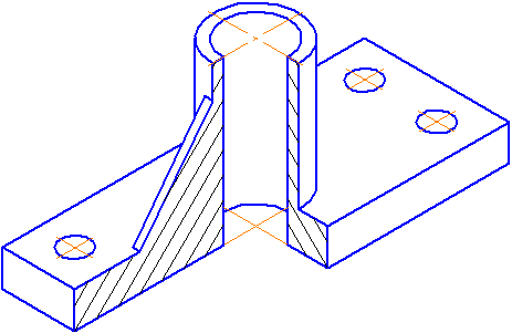
Figure 4.4 - Image of a part in a rectangular isometric projection
4.1.2. Dimetric projection
The position of the axonometric axes is shown in Figure 4.5.
To construct an angle approximately equal to 7º10´, a right triangle is constructed, the legs of which are one and eight units of length; to construct an angle approximately equal to 41º25´- the legs of the triangle, respectively, are equal to seven and eight units of length.
Distortion coefficients along the OX and OZ axes k=n=0.94 and along the OY axis - m=0.47. When rounding these parameters, it is assumed k=n=1 and m=0.5. In this case, the dimensions of the axes of the ellipses will be: the major axis of the ellipse 1 is equal to 0.95D and ellipses 2 and 3 - 0.35D(D is the diameter of the circle). In Figure 4.5, the major axes of ellipses 1, 2, and 3 are angled 90º to the OY, OZ and OX axes, respectively.
An example of a rectangular dimetric projection of a conditional part with a cutout is shown in Figure 4.6.
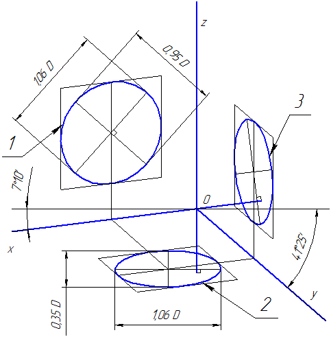
Figure 4.5 - Axonometric axes in a rectangular dimetric projection
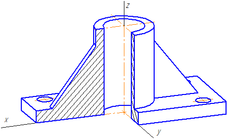
Figure 4.6 - Image of a part in a rectangular dimetric projection
4.2 Oblique projections
4.2.1 Frontal dimetric projection
The position of the axonometric axes is shown in Figure 4.7. It is allowed to use frontal dimetric projections with an angle of inclination to the OY axis equal to 30 0 and 60 0 .
The coefficient of distortion along the OY axis is equal to m=0.5 and along the axes OX and OZ - k=n=1.
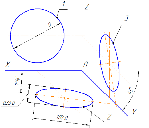
Figure 4.7 - Axonometric axes in oblique frontal dimetric projection
Circles lying in planes parallel to the frontal projection plane are projected onto the XOZ plane without distortion. Major axes of ellipses 2 and 3 are equal 1.07D, and the minor axis is 0.33D(D is the diameter of the circle). The major axis of the ellipse 2 makes an angle with the OX axis 7º 14´, and the major axis of the ellipse 3 makes the same angle with the OZ axis.
An example of an axonometric projection of a conditional part with a cutout is shown in Figure 4.8.
As can be seen from the figure, this part is located in such a way that its circles are projected onto the XOZ plane without distortion.
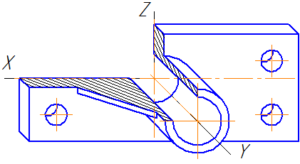
Figure 4.8 - Image of a part in an oblique frontal dimetric projection
4.3 Building an ellipse
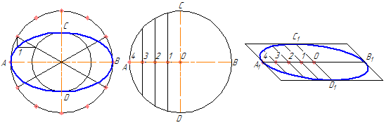
4.3.1 Building an ellipse along two axes
On these axes of the ellipse AB and CD, two concentric circles are built as on diameters (Figure 4.9, a).
One of these circles is divided into several equal (or unequal) parts.
Radii are drawn through the division points and the center of the ellipse, which also divide the second circle. Then straight lines parallel to the lines AB are drawn through the division points of the great circle.
The intersection points of the corresponding lines will be the points belonging to the ellipse. Figure 4.9, a shows only one desired point 1.
a B C
Figure 4.9 - Construction of an ellipse along two axes (a), along chords (b)
4.3.2 Building an ellipse from chords
The diameter of the circle AB is divided into several equal parts, in Figure 4.9, b there are 4 of them. Through points 1-3, chords are drawn parallel to the diameter CD. In any axonometric projection (for example, in an oblique dimetric projection), the same diameters are depicted, taking into account the distortion factor. So in Figure 4.9,b A 1 B 1 \u003d AB and C 1 D 1 \u003d 0.5CD. The diameter A 1 B 1 is divided into the same number of equal parts as the diameter AB, through the obtained points 1-3, segments are drawn equal to the corresponding chords multiplied by the distortion factor (in our case, 0.5).
4.4 Cross-hatching
The hatching lines of sections (sections) in axonometric projections are drawn parallel to one of the diagonals of the squares lying in the corresponding coordinate planes, the sides of which are parallel to the axonometric axes (Figure 4.10: a - hatching in rectangular isometry; b - hatching in oblique frontal dimetry).

a b
Figure 4.10 - Examples of hatching in axonometric projections
 Two heads and six legs; four walk, and two lie still
 Self-esteem - what is it: concept, structure, types and levels
 Cassandra's Path, or Pasta Adventures War on Earth and Underground