Normative method of aerodynamic calculation of boiler installations of Tskti named after and Polzunov. Calculation of the gas-air path of boiler plants
Industrial heat power engineering
Course work
Topic: "Aerodynamic calculation of boiler plants"
Assignment for the course work "Aerodynamic calculation of boiler plants"
|
Name of the column |
Designation |
Meaning |
C I unit |
||
|
Fuel consumption |
|||||
|
Theoretical fuel consumption |
|||||
|
The volume of flue gases at the outlet of the furnace |
|||||
|
The volume of flue gases in front of the air heater |
|||||
|
The volume of flue gases after the air heater |
|||||
|
Flue gas temperature before superheater |
|||||
|
Flue gas temperature before economizer |
|||||
|
Flue gas temperature in front of the air heater |
|||||
|
Flue gas temperature |
|||||
|
Air suction in the furnace |
|||||
|
Air leakage from the air heater |
|||||
|
The coefficient of excess air in the furnace |
|||||
|
Average air speed |
|||||
|
Flue gas average velocity |
|||||
|
Cold air temperature |
|||||
|
Heated air temperature |
|||||
|
Performance safety factor |
Introduction
The purpose of this course work is the aerodynamic calculation of the boiler plant. To organize the combustion process, boilers are equipped with draft devices: blowers that supply air to the furnace, smoke exhausters to remove flue gases from the boiler, as well as a chimney, which is usually installed common to all boilers. Modern boiler units have individual smoke exhausters and blowers.
To select draft devices, an aerodynamic calculation of the boiler unit is performed, which consists of two parts. First, the calculation of the air path of the boiler unit is performed. After this calculation, the selection of a blower fan is carried out. The second part includes the calculation of the gas path. The main task of this calculation is the selection of a smoke exhauster and a chimney.
The initial data for performing the aerodynamic calculation are the results of the thermal calculation, which precedes the aerodynamic calculation.
1. Theoretical part
A boiler plant is a complex of devices located in special rooms and serving to convert the chemical energy of fuel into thermal energy of steam or hot water. Each boiler installation consists of separate elements - devices. Some devices are basic, and the boiler room cannot function without them, others can be called additional, and without them the installation will work, but with a high fuel consumption, and, consequently, with a lower efficiency; the third - mechanisms and devices that perform auxiliary functions.
The main elements of the boiler room include:
boilers filled with water and heated by combustion heat.
A boiler is a heat exchange device in which heat from hot products of fuel combustion is transferred to water. As a result, in steam boilers, water is converted into steam, and in hot water boilers it is heated to the required temperature.
furnaces in which fuel is burned and flue gases heated to high temperatures are obtained.
The combustion device is used to burn fuel and convert its chemical energy into the heat of heated gases. Feeding devices (pumps, injectors) are designed to supply water to the boiler.
· gas ducts through which flue gases move and, in contact with the walls of the boiler, give off their heat to the latter;
· chimneys, with the help of which flue gases move through the gas ducts, and then, after cooling, are removed into the atmosphere.
Without the listed elements, even the simplest boiler installation cannot work.
Auxiliary elements of the boiler room include:
· devices of fuel transfer and dust preparation;
· ash collectors used in the combustion of solid fuels and designed to clean flue gases and improve the condition of atmospheric air near the boiler house;
· blowers necessary for supplying air to the furnace of boilers;
· smoke exhausters-fans, contributing to increased traction and thereby reducing the size of the chimney;
feeding devices (pumps) necessary for supplying water to the boilers;
· Feedwater treatment devices that prevent scale formation in boilers and their corrosion;
· the water economizer is used for heating the feed water before it enters the boiler;
· the air heater is designed to heat the air before it enters the furnace with hot gases leaving the boiler unit;
· thermal control devices and automation equipment that ensure the normal and uninterrupted operation of all parts of the boiler room.
Boiler plants, depending on the type of consumer, are divided into energy, production and heating and heating. According to the type of heat carrier produced, they are divided into steam (for generating steam) and hot water (for generating hot water).
Power boiler plants produce steam for steam turbines in thermal power plants. Such boiler houses are equipped, as a rule, with boiler units of large and medium power, which produce steam with increased parameters.
Industrial heating boiler plants (usually steam) produce steam not only for industrial needs, but also for heating, ventilation and hot water supply.
Heating boiler plants (mainly water-heating, but they can also be steam) are designed to service heating systems, hot water supply and ventilation of industrial and residential premises.
Depending on the scale of heat supply, heating boiler houses are divided into local (individual), group and district.
Local heating boiler houses are usually equipped with hot water boilers with water heating up to a temperature of no more or steam boilers with an operating pressure of up to. Such boiler houses are designed to supply heat to one or more buildings.
Group heating boilers provide heat to groups of buildings, residential areas or small neighborhoods. Such boiler houses are equipped with both steam and hot water boilers, as a rule, with higher heat output than boilers for local boiler houses. These boiler houses are usually placed in special buildings.
District heating boiler houses are designed to supply heat to large residential areas; they are equipped with relatively powerful hot water and steam boilers.
A steam boiler is a pressure vessel in which water is heated and converted into steam. The thermal energy supplied to the steam boiler may be fuel, electrical, nuclear, solar or geothermal energy. There are two main types of steam boilers: gas-tube and water-tube.
Hot water boiler plants are designed to produce hot water used for heating, hot water supply and other purposes. A hot water boiler house has one heat carrier - water, in contrast to a steam boiler house, which has two heat carriers - water and steam. In this regard, in a steam boiler house, it is necessary to have separate pipelines for steam and water, as well as a tank for collecting condensate.
Hot water boilers differ depending on the type of fuel used, the design of boilers, furnaces, etc. The structure of both a steam and a water-heating boiler plant usually includes several boiler units, but not less than two and not more than four or five. All of them are interconnected by common communications - pipelines, gas pipelines, etc.
Installations operating on nuclear fuel, the feedstock of which is uranium ore, are becoming more widespread.
Aerodynamic calculation of a boiler plant is a calculation, as a result of which the aerodynamic resistances of the gas-air path are determined both for the installation as a whole and for its various elements. Normal operation of the boiler plant is possible under the condition of continuous supply of air to the furnace and removal of combustion products into the atmosphere after they have been cooled and cleaned from solid particles. The supply and removal of combustion products in the required quantities are provided by the construction of gas-air systems with natural and artificial draft. In systems with natural draft, used in low-power boiler plants with low aerodynamic resistance along the gas path, the resistance to the movement of air and combustion products is overcome by the draft created by the chimney. When the boiler plant is equipped with an economizer and an air heater and its resistance along the gas path is significantly higher than 1 kPa, the gas-air path system is equipped with fans and smoke exhausters. In a boiler plant with a balanced draft, the air path operates under excess pressure created by fans, and the gas path under vacuum; in this case, the smoke exhauster provides a vacuum in the furnace equal to 20 Pa. The calculation of the resistance of the gas and air paths of steam and hot water boilers is performed in accordance with the standard method. When changing the steam capacity of the boiler plant or the type of fuel burned, the path resistances are recalculated.
The movement of gases in the gas-air path is accompanied by a loss of energy spent on overcoming the forces of friction of the gas flow on solid surfaces. The resistances arising from the movement of the flow are conventionally divided into: frictional resistance during the flow of the flow in a straight channel of constant cross section, including the longitudinal washing of the tube bundle; local resistances associated with a change in the shape or direction of the flow, which are conditionally considered to be concentrated in one section and not including frictional resistance.
The schemes of the gas and air paths should be simple and ensure reliable and economical operation of the installation. It is advisable to use an individual layout of the tail heating surfaces, ash collectors and draft devices without bypass gas ducts and connecting collectors. On extended straight sections, round gas ducts are recommended as less metal-intensive and with less consumption of thermal insulation compared to square and straight ones. Gas ducts of steam and hot water boilers operating on explosive fuels should not have areas in which deposits of unburned particles, soot, and poorly ventilated areas are possible. The total pressure drop in a boiler plant is the sum of the pressure drops across the individual elements. For units operating under vacuum, the total differential is determined separately for the air and gas paths. In the pressurized boiler, the total gas-air resistance is calculated.
2. Aerodynamic calculation of the air path
The purpose of the calculation is the selection of a blower fan. To select a fan, you need to know m3 / h, and pressure Hv, Pa. All initial data (air temperature, open area, average speed, etc.) are taken from the thermal calculation.
Fan performance is determined by the formula:
where v1 is the safety factor for performance;
Vв - the amount of air required to supply the boiler furnace, m3 / h,
then, m3/h
The values of Vr, V0, bt, Dbt, Dvvp, txv, v1 are taken from the initial data.
1. an axonometric diagram of the air path of the boiler unit is drawn up from the air intake pipe to the very last burner;
2. the entire tract is divided into sections (the sections must have a constant flow rate and an average speed);
3. for each section, pressure losses from friction and from local resistances are determined;
found The pressure developed by the fan is found by the formula:
where v2 - head safety factor, v2 = 1.1;
DRV - aerodynamic resistance of the air path of the boiler unit.
The calculation of DRV, Pa, is carried out in the following sequence:
4. The sum of pressure losses UDP is added to the resistance of the burner device DRgor: .
2.1. Axonometric diagram of the air path
Figure 1 shows an axonometric diagram of the air path. The numbers correspond to the sections into which the air path is divided to simplify the calculation.
Fig.1. air path
2.2. Calculation of pressure losses in the air duct
Friction pressure loss:
Pressure losses from local resistances DRms, Pa, are determined by the formula:
where l is the coefficient of friction, depending on the Reynolds number and the roughness coefficient of the channel walls ke, l \u003d 0.02 - for steel pipes;
l -- section length, m;
Uo - the sum of the coefficients of local resistances;
de - equivalent diameter of the air channel section, m.
where F is the open area of the channel, m2;
P - channel perimeter, m;
c - air density, kg / m3,
where t is the air temperature, °C;
co -- air density under normal conditions, kg/m3;
W -- air speed m/s.
where VВ is the air consumption in this area, m3/h;
F is the cross-sectional area of the pipe, m2.
2.3 Section 1-2 calculation
On section 1-2 there are: an air intake pipe, a damper, a suction pocket, as well as a diffuser (confuser) for connecting the pipe with a pocket that directs air to the fan.
Pipe 1120x1120 mm.
The area of the living section is equal to:
The equivalent duct diameter is:
The density of cold air is:
The dynamic head is:
Coefficients of local resistance in the air intake pipe 0.3 and in the damper 0.1
In order to determine the coefficient of local resistance of the connection of the air duct to the suction pocket, it is necessary to know the dimensions of the inlet of the pocket, which depend on the diameter of the outlet. The outlet of the pocket is directly connected to the inlet of the blower fan. Thus, you should choose a fan, but for this you need to know the pressure that it will develop in the air path. The pressure of the fan depends on the pressure loss in the entire air path, therefore, having calculated the pressure loss in the sections of the air path after the fan, I determine the approximate value of the pressure. Based on this pressure value and the air flow rate QB, we select the type of blower fan. Then, having calculated the pressure loss in the connection of the section 1-2 pipe with the suction pocket and the connection of the section 2-2" pipe with the fan outlet, we make a correction to the pressure created by the fan. If the fan cannot create such a pressure, then another fan must be selected.
Then the pressure loss in the air intake pipe and the damper will be:
Approximate losses in the area:
blower fan gas burner
2.4 Calculation of section 2-2?
This section of the air duct connects the fan outlet to the air heater. In this section, the air flow rate and density remain the same as in section 1-2, i.e. VВ = 66421.929 m3/h. If we take the dimensions of the air duct in the section as in section 1-2, i.e. 1120 × 1120 mm, then the air speed and dynamic pressure will remain unchanged.
We calculate friction losses:, Pa
2.5. Calculation air heater resistance
The air heater is a bundle of linear pipes. Flue gases pass inside the pipes (from bottom to top or from top to bottom), which are washed from the outside with heated air. The location of the pipes can be either in-line or staggered. Accordingly, the resistance of the air heater will be the resistance of the transversely washed in-line or staggered pipe bundle.
Average air temperature in the air heater:
Let's recalculate the air flow V and its density for the air heater:
In the aerodynamic calculation, we choose: the number Z1 = 49 and Z2 = 79, the pitch S1 = 65 mm and S2 = 55 mm of pipes in the transverse and longitudinal sections, respectively, the diameter d = 40 mm, the height h = 2600 mm and the wall thickness s = 4 mm pipes.
The width of the air heater is:
The length of the air heater is determined by the formula:
The air velocity in the air heater is:
The arrangement of pipes in the air heater is staggered, the pipes are smooth.
The resistance coefficient of a smooth-tube staggered bundle is determined depending on:
From the relative transverse pitch of the pipes in the bundle
From coefficient
The resistance of a staggered tube bundle is calculated by the formula:
where - correction factor, depends on the diameter of the pipes;
Correction factor, depends on the relative steps of the pipes and;
The graphical resistance of one row of pipes depends on the speed and temperature of the flow.
At d=40 mm coefficient =0.96,
at \u003d 1.625 and coefficient \u003d 1.1
By speed and average temperature we determine: \u003d 0.8 mm of water.
Then: mm wd.st. = 662.999, Pa
The connection of the 2-2 "section pipe to the air heater occurs with the help of a sharp expansion: the initial section is 1120x1120 mm, the final one is 3350x2000 mm.
The drag coefficient during a sharp expansion of the direct channel is determined depending on the ratio of the smaller section to the larger one:
Then new = 0.75.
Pressure loss during abrupt expansion: , Pa
The pressure loss in the section, taking into account the losses in the air heater, is:
2.6 Calculation of section 2?-3
This section of the air duct connects the outlet of the air heater to the pipelines supplying heated air to the burners.
The volume of heated air VВ, m3/h, supplied to the furnace, is determined by the formula:
where tpv is the temperature of the heated air, °C.
The cross-sectional area is:
Pipe 1250?1600, mm
Air velocity in the pipe: , m/s
The density of heated air is:
Dynamic head is: , Pa
We calculate friction losses: , Pa
The outlet of the air heater is connected to the section pipe by means of a pyramidal confuser (3350x2000 mm > 1250x1600 mm).
The coefficient of local resistance of the pyramidal confuser is determined depending on the larger angle of narrowing b. A greater angle of constriction will be when the width of the air heater is reduced to the width of the pipeline
We receive.
Since the angle is 20°< б < 60°, то коэффициент местного сопротивления конфузора о = 0,1.
There is also a 90° turn on the section, the coefficient of local resistance of which is o = 1.
The total pressure loss in the section is equal to:
2.7 Calculation of section 3-4
Based on the fuel consumption, we determine the number of burners used in the boiler plant. To do this, we divide this flow rate by the gas capacity of the burner. Let's take the GPM-16 burner, which has a gas capacity of 1880 m3/h.
Then the number of burners is: 13950/1880 = 7.42, i.e. we install 8 burners.
To carry out the air supply to the burners, at the beginning of section 3-4 we will put a symmetrical separating tee. Each branch of the tee directs the air flow to one burner. Since the branches to the burners are symmetrical, it is enough to calculate the losses in one branch to determine the pressure losses in section 3-4.
For calculation, we divide section 3-4 into two: 1 "- section before the flow branch to the first burner; 2" - section after the branch. The resistance of section 3-4 will be the total resistance of these sections.
Plot 1"
The the section contains a 90° turn in a symmetrical tee. Since the flow in the tee is divided into two equal parts, the volume of air passing through the section is equal to half the flow in the previous section:
According to the area obtained, we select the dimensions and type of pipe:
pipe 1250800, mm
Calculate the air velocity in the pipe:
The density of heated air is = 0.616, kg/m3
Dynamic head: , Pa
Friction pressure loss: , Pa
The coefficient of resistance when turning in a symmetrical tee is determined in the same way as for a side branch in an asymmetrical tee with
where Fc is the open area of the pipe before the branch; Fb- area of the free section of the lateral branch of the tee; FP is the area of the open section of the pipe in the passage of the tee.
If the speeds are equal before the branch and in the side branch at a branch at an angle of 90°, the coefficient of local resistance.
Pressure loss in local resistances: , Pa
The total pressure loss in section 1" is
Plot 2"
On the In this section, there is a separating asymmetrical tee, the area of the branch in which is equal to the area of the passage and, accordingly, the volumes of air passing through the passage and the branch are equal.
The volume of air passing through the passage of the tee (section 2 ") and through the branch is equal to
cross-sectional area: , m2
According to the area obtained, we select the dimensions and type of pipe:
pipe 12500.4, mm
We calculate the air velocity in the pipe: , m/s
Heated air density: =0.616, kg/m3
Dynamic head: , Pa
Friction pressure loss: Pa
The coefficient of local resistance in the passage of the tee is determined depending on the ratio of velocities after and before the branch. When they are equal.
Pressure losses from local resistances are:
Total pressure loss in section 2": , Pa
The total resistance of section 3-4 is taken equal to:
2.8 Section calculation 4-5
In this section, the air duct is connected to the burners.
We calculate the resistance of the air ducts to each of the burners on one branch of section 3-4, and then, choosing the section with maximum resistance, we obtain losses in section 4-5.
2.8.1 supply to first burner
The the inlet is a branch of an asymmetrical tee at the beginning of section 3-4 (2") at an angle of 45o, on which there is also a 45o turn and a connection with a burner inlet.
The volume of air passing through section 4-5 is, m3 / h, the cross-sectional area is
According to the area obtained, we select the dimensions and type of pipe:
pipe 630x800, mm
We calculate the air velocity in the pipe: m/s.
The density of heated air is =0.616, kg/m3.
Dynamic head: , Pa.
Friction pressure loss: , Pa.
The coefficient of local resistance of the side branch of the tee at an angle of 45o is determined depending on the ratio of velocities after and before the branch. When they are equal, the coefficient of local resistance.
At the end of section 4-5, the air duct is connected to the burner inlet with dimensions of 990x885 mm. To connect a pipe 630x800 mm, it is necessary to install a diffuser.
The coefficient of local resistance of the diffuser in the direct channel is calculated by the formula
where is the coefficient of completeness of impact, depending on the angle of opening of the diffuser;
The coefficient of resistance during sudden expansion is determined depending on the ratio of the smaller section to the larger one:
Then according to the schedule:
When expanding the 630 mm side to 990 mm, you get a larger angle than when expanding the 800 mm side to 885 mm, so I determine by this side. The length of the diffuser is assumed to be 500mm.
Opening angle. I determine from the angle
The pressure loss from local resistances is
The total pressure loss at the inlet to the first burner is
2.8.2 supply to second burner
On the In this section of the air duct there is a 90° turn from section 3-4 (2") and a diffuser connecting the pipe to the burner inlet.
The volume of air passing through this section is equal to the volume of air passing through section 3-4 (2"), i.e. 28547.678m3 / h. The dimensions of the pipeline remain unchanged compared to section 3-4 (2"), therefore , the air velocity and dynamic pressure remain unchanged.
Friction pressure losses are
The coefficient of local resistance to rotation at an angle of 45o.
The connection of the pipeline to the second burner is similar to the connection to the first burner, respectively, the coefficient of local resistance has the same value, i.e. .
Pressure loss in the supply to the second burner
The pressure loss in section 4-5 is assumed to be equal to the resistance of the supply to the first burner: , Pa.
Approximate value of pressure loss in the air path:
2.9 Burner resistance
The resistance of the burner Dhgor, Pa, is calculated by the formula:
where W is the air speed in the burner, m/s,
where Fgor is the area over which the air moves in the burner,
Dynamic head: , Pa
Burner resistance: Pa
2.10 Fan selection
The aerodynamic resistance of the air path of the boiler unit is approximately equal to: , Pa
The pressure developed by the fan is equal to:
Pa = 378.665 mm water column
Using the performance of the blower fan:
Qw = 69747, 025, m3/h
HB = 378.7 mm water column,
created by it, according to the summary graph of characteristics, we select a fan. We choose a VDN-17 blower fan with a rotation speed of 980 rpm.
In the table of design characteristics of the fan, we find the dimensions of the inlet and outlet of the fan: d = 1700mm; a = 630mm; b = 1105mm.
After choosing a fan, we calculate the pressure loss in sections 1-2 and 2-2". After recalculating the pressure loss, we find the true value of the pressure that the fan should create.
2.11 Recalculation of plot 1-2
Pocket inlet dimensions:
a = 1.8 db = 1.8 1700 = 3060, mm
b = 0.92 dv = 0.92 1700 = 1564, mm
The pipeline of section 1-2 is connected to the pocket using a diffuser (1120x1120 mm > 1564 × 3060 mm).
The coefficient of local resistance of the pyramidal diffuser is determined depending on the larger opening angle of the diffuser and on the ratio of the smaller section to the larger one. A larger opening angle will be when increasing the side of the pipeline with a size of 1120 mm to the side of the pocket with a size of 3060 mm.
Opening angle b = 2arctg 0.32 = 39°. According to the angle b we find cp \u003d 1.1
The ratio of the smaller section to the larger one is:
then new = 0.6, .
The pressure loss in the diffuser is: , Pa
The pressure loss in the suction pocket is calculated from the air flow velocity in the pocket: , m/s.
The coefficient of local resistance in the pocket is 0.1.
Pressure losses from local resistances in the area are:, Pa.
Total losses in section 1-2: , Pa.
2.12 Section recalculation 2-2"
The pipe is connected to the fan outlet by means of a sharp expansion (630x1105 mm > 1120x1120 mm).
The coefficient of local resistance during a sharp expansion of the pipe is determined depending on the ratio of the area of \u200b\u200bthe smaller section to the larger one:
then the coefficient of local resistance of a sharp expansion of s = 0.2.
The pressure loss DR, Pa, from local resistance after the fan is determined by the formula:
where W is the air velocity at the outlet of the fan.
Air velocity at the outlet of the fan: , m/s
Pressure losses from local resistances in the section are:
Total losses in the section: , Pa
Having recalculated the pressure losses in sections 1-2 and 2-2", we obtain the true value of pressure losses in the air path.
Let's combine the results obtained when calculating pressure losses in all sections in a table (Table 1):
Table 1. Calculation results of pressure losses in all sections
The pressure loss throughout the air path is:
The pressure developed by the fan:
Pa \u003d 397.275, mm of water. Art.
Using the performance of the blower fan
Qw = 69747.025, m3/h
Hb \u003d 397.275, mm of water. Art.,
created by him, according to the graph of the aerodynamic characteristics of the VDN-17 blower fan with a rotation speed of 980 rpm, we find the value of the fan efficiency: h = 0.81.
The power consumed by the fan Nv, kW, is calculated by the formula:
where Qv -- fan performance, m3/h;
Hv - pressure created by the fan, Pa;
sv -- Fan efficiency, %.
3. Aerodynamic calculation of the gas path
The purpose of the calculation is the selection of a smoke exhauster and a chimney. To select a smoke exhauster, it is necessary to know its performance Qd and the pressure Hd created by the pump.
The performance of the smoke exhauster Qd, m3/h, is determined by the formula:
where s1 is the safety factor for performance: s1 = 1.05;
Vdg - the volume of flue gases removed from the boiler by a smoke exhauster, m3 / h,
where the volume of flue gases, is the temperature of the gases leaving the boiler unit.
then the performance of the smoke exhauster Qd is equal to:
The pressure created by the smoke exhauster is determined by the formula:
where s2 is the safety factor for consumption, s2 = 1.1;
k2 is a coefficient that takes into account the difference between the operating conditions of the smoke exhauster and the conditions for which the aerodynamic characteristic of the smoke exhauster is compiled,
where thar \u003d 100 ° С is the temperature of the flue gases, for which the characteristic of the smoke exhauster is compiled,
DRka = DRc + DRp/p + DRv ek + DRv/p + DRg/x + DRd tr ± DRs/t,
where DRka is the pressure loss along the gas path of the boiler unit, Pa;
DRk - aerodynamic resistance of the boiler itself, Pa;
DRp/n -- aerodynamic resistance of the superheater, Pa;
DRv eq - aerodynamic resistance of the water economizer, Pa;
DRv/p - aerodynamic resistance of the air heater, Pa;
DRg/x - aerodynamic resistance of the gas ducts connecting the boiler with the tail heating surfaces, as well as the smoke exhauster and the chimney between themselves, Pa;
DRD tr -- aerodynamic resistance of the chimney, Pa;
DPS / t - self-traction developed by a chimney, Pa.
3.1 Axonometric diagram of the gas path
Figure 2 shows an axonometric diagram of the gas path. The numbers correspond to the sections into which the gas path is divided to simplify the calculation.
Fig.2. gas path
Legend:
I - boiler;
II - superheater;
III - water economizer;
IV - air heater;
V - smoke exhauster;
VI - chimney;
3.2. Boiler aerodynamic resistance
The boiler consists of a furnace lined inside with screen heating surfaces through which water circulates. Let us take the overall dimensions of the boiler 11 × 15 × 18 m.
where DRr is the vacuum at the outlet of the furnace (20 ~ 30 Pa). Let's take DRr = 25 Pa;
DR4pov - pressure loss during four sharp turns at an angle of 90 ° in the chamber, Pa;
DPkp -- pressure loss in the boiling beams, Pa;
DRrs - pressure loss with a sharp narrowing at the inlet to the channel of the gas path, Pa.
The volume of flue gases passing through the boiler:
The area of the boiler chamber is equal to:
Flue gas velocity in the boiler chamber:
Flue gas density c, kg/m3, is calculated by the formula:
Dynamic head: , Pa
Pressure losses during four sharp turns at an angle of 90° (o = 1) are: , Pa
3.3 Boiler beam resistance
The boiler bundle in the boiler is formed from the screen pipes of the rear wall of the boiler, on which there are Z tubes with a diameter of d = 50 mm with a step of 60 mm. The number of tubes on the back wall is:
Let us compose a boiler bundle of in-line type from Z2 = 3 rows with a pitch of S2 = 70 mm, then in each row there will be Z1 = 83 tubes arranged with a pitch of S1 = 3 60 = 180 mm. The beam height is 3000 mm. By the number of tubes in the cross section and their pitch, we specify the width of the boiler:
The resistance coefficient of a smooth-tube in-line bundle of pipes is determined depending on:
from the relative transverse pitch of the pipes,
on the relative longitudinal pitch of the pipes,
from the coefficient.
When y1 > y2 and 1 ? sh? 8 the coefficient of local resistance of the in-line pipe bundle o is determined by the formula
at y1 = 3.6 coefficient Cy = 0.495.
The cross-sectional area along which the flue gases move in the beam is equal to:
The flue gas velocity in the beam is
At W = 3.012 coefficient lim = 0.67,
at limit = 0.67 and w = 6.5, the coefficient CRe = 0.24. .
The pressure loss in the tube bundle is:
The coefficient of local resistance at the entrance to the channel with straight edges flush with the wall is 0.5,
then pa
As a result, we get: , Pa
3.4 Superheater aerodynamic drag
The location of the coils in the superheater can be either in-line or staggered. Accordingly, the resistance of the superheater is the resistance of the in-line or staggered tube bundles.
We accept: the arrangement is staggered, the pipes are smooth. The number of pipes in the cross section Z1 = 104, and along the flue gases Z2 = 59. The pipes are located respectively at a distance of S1 = 60 mm and S2 = 45 mm. The pipe diameter is 32 mm. The height of the pipes is 4000 mm.
Superheater dimensions:
height h = 4000, mm;
width b = (Z1 + l) S1 = (l04 + l) 60 = 6300, mm;
· length l = (Z2+1) · S2 = (59 + l) · 45 = 2700, mm.
The drag coefficient of a smooth-tube staggered bundle is determined depending on the ratios:
Resistance of a chess bundle of pipes Dh, mm of water. Art., at 0.1? C? 1.7 is found by the formula:
At d = 32 mm Cd = 1.005,
at y1 = 1.88 and coefficient Cs = 1.07.
The area of the beam section is equal to:
Average flue gas temperature in the superheater:
The flue gas density in the superheater is:
The volume of flue gases in the superheater:
The flue gas velocity in the superheater is:
By speed and average temperature, we determine Dhgr, mm of water. st.:
Dhgr = 0.6, mm w.c. Art.
Superheater resistance:
Дh = , mm w.c. = 379.771, Pa
3.5 Aerodynamic resistance of the water economizer
The steel serpentine economizer is a bundle of pipes assembled from steel coils with a diameter of 28 or 32 mm, with walls 3 or 4 mm thick. Flue gases transversely wash the coils. The location of the coils can be corridor and staggered. (They adopted a staggered arrangement of coils).
The number of pipes in the cross section Z1 = 74, and along the flue gas Z2 = 74. The pipes are located respectively at a distance of S1 = 70 mm and S2 = 40 mm. The diameter of the pipes is 32 mm, the height of the pipes is 3500 mm.
Economizer dimensions:
length (height of the boiling beam) h = 3500, mm.
Width (width of the boiling beam), mm;
height (boiling beam length), mm;
The resistance of a staggered tube bundle depends on;
Resistance of a chess bundle of pipes Dh, mm of water. Art., at y1? 3 and 1.7? c? 6.5 is calculated by the formula:
At d = 32 mm, the coefficient Cd = 1.005,
with y1 = 2.19 and y2 = coefficient CS = 1.07.
Beam area:
The average flue gas temperature in the water economizer is:
The average volume of flue gases leaving the economizer:
The volume of flue gases in the economizer:
The flue gas velocity in the economizer is:
Based on the speed W = 9.351 m/s and the average temperature °C, we determine Dhgr, mm of water. Art.: Dhgr = 0.69.
Economizer resistance:
mm w.c. article = 545.92, Pa
3.6 Aerodynamic resistance of the air heater
The resistance of the air heater is the sum of the frictional resistance in the pipes and the resistance of entering and exiting the pipes. The parameters of the air heater are taken from the air path of the boiler.
Air heater dimensions:
h = 2600 mm,
b = 3250 mm,
l = 4950mm;
Pipe diameter and thickness: d = 40 mm; s = 4 mm;
Number of pipes: Z1 = 49, Z2 = 79;
Distance between pipe axes: S1 = 65 mm, S2 = 55 mm;
The area of the beam section is equal to:
Average flue gas temperature in the air heater:
The average volume of flue gases leaving the air heater:
The volume of flue gases in the air heater:
The speed of movement of flue gases in the air heater:
Friction resistance in pipes is calculated by the formula:
where Dh?gr -- depends on the average temperature of the flow and on the flow rate, Dh?gr = 22, mm of water. st./m;
Csh -- correction factor for roughness, Csh = 0.92;
l -- total length of pipes, m;
mm w.c. Art. = 982.844, Pa
The resistance at the entrance to the pipes and at the exit from them is calculated by the formula:
where m is the number of individual cubes successively located along the gas, m = 1;
ovx and ovy - the coefficients of entry and exit are determined depending on the ratio of the total area of the free section of the pipes to the area of the free section of the gas duct before and after the air heater.
At = 0.368, the coefficients of local resistance at the inlet and outlet of flue gases into the air heater tubes are, respectively, oxx = 0.33 and oxx = 0.45.
Flue gas density in the air heater:
Dynamic head:
then pa
As a result, the resistance of the air heater is equal to:
3.7 Aerodynamic resistance of gas ducts in the tract
3.7.1 Calculation site 1-2
The the flue section connects the boiler outlet to the superheater.
The volume of flue gases passing through the section is equal to the volume of flue gases leaving the boiler, i.e. V1-2 = 356854.286, m3/h.
Cross-sectional area:
According to the area obtained, we select the dimensions and type of pipe:
pipe 3550?2800, mm.
Living area:
Dynamic head:
We calculate friction losses:
The pipe is connected to the boiler outlet (3550×2800 mm) without local resistance. The connection of the pipe section 1-2 to the superheater occurs with the help of a sharp expansion: the initial section is 3550 × 2800 mm, the final one is 6300 × 4000 mm.
At = 0.394, the local resistance coefficients ovx = 0.29 and ov = 0.39, Pa
3.7.2 Calculation site 3-4
The the flue section connects the superheater to the water economizer.
The volume of flue gases passing through the section is equal to:
Cross-sectional area:
According to the area obtained, we select the dimensions and type of pipe:
pipe 3350?2240, mm
Living area:
Equivalent flue diameter:
Flue gas velocity in the pipe:
Flue gas density at 755 °С:
Dynamic head:
Calculate friction losses
The outlet of the superheater is connected to the pipe using a pyramidal confuser (6300×4000 mm > 3350×2240 mm). The coefficient of local resistance of the pyramidal confuser depends on the larger taper angle b, which in this case will be when the superheater width is reduced to the pipe width:
We get b \u003d 58 °. Since the angle is 20°< б < 60°, то коэффициент местного сопротивления конфузора о = 0,1.
The coefficient of local resistance to rotation at an angle of 90 ° o \u003d 1.
The pipe is connected to the inlet of the water economizer using a sharp expansion (3350×2240 mm > 5250×3500 mm).
The ratio of the area of the smaller section to the area of the larger section is:
then ov = 0.4.
Pressure losses in local resistances are:
Total pressure loss in the section:
3.7.3 Calculation site 5-6
The the flue section connects the water economizer with the air heater.
The volume of flue gases passing through the section is equal to:
Cross-sectional area:
According to the area obtained, we select the dimensions and type of pipe:
pipe 2000?3550, mm
Living area:
Equivalent flue diameter:
Flue gas velocity in the pipe:
Flue gas density at 545°C:
Dynamic head:
We calculate friction losses:
The outlet of the water economizer is connected to the pipe using a pyramidal confuser (5250×3500 mm > 3550×2000 mm). A larger angle of constriction in this confuser will be when the width of the water economizer is reduced to the width of the pipe:
We get b \u003d 53.13 °. Since 20°< б < 60°, то коэффициент местного сопротивления конфузора о = 0,1.
At the end of section 5-6, the pipe is connected to the air heater inlet (4950 × 3250 mm). To connect a pipe 3350×2000 mm, it is necessary to install a pyramidal diffuser.
The coefficient of local resistance of the diffuser in the direct channel is calculated by the formula.
The ratio of the smaller section to the larger one is:
Then new = 0.39.
When expanding a side with a size of 3350 mm to 4950 mm, a larger angle is obtained than when expanding a side with a size of 2000 mm to 3250 mm, therefore, cp is determined from this side. The length of the diffuser is assumed to be 3000 mm.
Opening angle: .
According to the angle b, we determine that cp = 0.86. .
The coefficient of local resistance of each of the two turns at an angle of 90 ° o \u003d 1
Pressure loss in local resistances:
Total pressure loss in the section:
3.7.4 Plot 7-8
The the flue section connects the air heater to the suction pocket, which directs the flue gases to the smoke exhauster.
There is 1 turn by 90° in this section Coefficient of local resistance to turn by 90° o = 1
The volume of flue gases passing through the site is equal to the volume of flue gases carried away by the smoke exhauster, i.e., m3 / h
Cross-sectional area:
According to the resulting area, we select according to GOST the dimensions and type of pipe:
pipe 1800 × 2240 mm
Living area:
Equivalent flue diameter:
Flue gas velocity in the pipe:
Flue gas density at 120 °C is:
Dynamic head:
Friction losses are:
Connecting the air heater to the pipe - using a confuser (2000? 3550 mm > 1800? 2240 mm). A larger constriction angle in this confuser will be when the air heater width is reduced to the pipe width:
We get b \u003d 47.2 °. Since 20°< б < 60°, то коэффициент местного сопротивления конфузора о = 0,1.
In order to calculate the pressure loss in the suction pocket and in the connection of the section pipe with the pocket, it is necessary to know the dimensions of the pocket inlet, which are determined depending on the size of the outlet, which is equal to the size of the inlet of the smoke exhauster. To do this, you need to choose a smoke exhauster. Let us determine the pressure loss in section 8-9 and in the chimney, as well as the draft in the chimney. We calculate the approximate pressure created by the smoke exhauster, according to which I will choose the exhaust fan. Then, recalculating the losses in sections 7-8 and 8-9, we determine the true value of the pressure created by the smoke exhauster. If the smoke exhauster cannot create such a pressure, then it is necessary to choose another one.
Pressure loss in the confuser:
Total approximate pressure loss in the section:
3.7.5 Plot 8-9
The the section of the flue connects the outlet of the smoke exhauster with the chimney.
There are 2 90° turns in this section. The coefficient of local resistance to rotation at an angle of 90 ° o \u003d 1.
The volume and density of flue gases passing through this section remain unchanged compared to section 7-8, if we take the dimensions of the pipeline in this section the same as in section 7-8, then the flue gas velocity will not change, and, accordingly, the dynamic head.
Friction loss:
The gas duct is connected to the chimney using a plinth with a single gas duct supply with dimensions:
b = 3350 mm; a = 0.9 h = 0.9 3350 = 3015 mm.
To connect the flue to the plinth, it is necessary to install a diffuser (1800x2240 > 3015x3350 mm).
Then w=0.4
Pressure losses in local resistances are:
The total pressure loss in the section is:
3.8 Aerodynamic calculation of the chimney
Let's choose a cylindrical, brick pipe. To calculate the pipe, it is necessary to set the rate of exit of flue gases from the pipe. Let W = =12m/s.
The area of the mouth of the pipe is equal to:
Knowing the area of the hole, you can find the diameter of the outlet:
According to GOST, we choose the closest value of the diameter to the obtained value: m.
According to the selected diameter of the mouth, we find the area of the mouth and the velocity of the flue gases in the pipe:
According to the diameter at the outlet of the pipe, according to a unified range of standard sizes of chimneys, we select the height of the chimney.
The flue gas density at 135 °C is c = 0.883 kg/m3.
The dynamic head is:
We calculate friction losses. Friction coefficient l = 0.05.
Losses from local resistances at the exit from the chimney (o = 1) are:
Total pressure loss in the chimney:
Self-pull in the pipe:
3.9 Choice of smoke exhauster
Adding pressure losses in all units and gas ducts, we obtain an approximate value of pressure losses in the gas path:
The pressure developed by the smoke exhauster is equal to:
Pa \u003d 219.54, mm of water. Art.
According to the performance of the exhauster
Qd = 157613.539, m3/h
Nd \u003d 219.54, mm of water. Art.,
which he creates, we select the D-20?2 smoke exhauster with a rotation speed of 590 rpm. Knowing the dimensions of the inlet and outlet of the smoke exhauster, one can find the pressure loss in sections 7-8 and 8-9.
3.10 Recalculation of plot 7-8
In front of the smoke exhauster there is a suction pocket with the dimensions of the inlet:
a = 0.92 dd = 0.92 2000 = 1840, mm;
b = 1.8 dd = 1.8 2000 = 3600, mm.
To connect a pocket measuring 1840×3600 mm to a pipe 1800×2240 mm of the section, it is necessary to install a confuser. A larger angle of constriction in this confuser will be at:
We get b \u003d 37.5 °. Since 20°< б < 60°, то коэффициент местного сопротивления конфузора о = 0,1.
The pressure loss in the confuser is determined by the flue gas velocity in a smaller section, i.e., by the flue gas velocity in the chimney.
Flue gas velocity in the chimney:
Resistance coefficient in the suction pocket o = 0.1
Pressure loss in diffuser and suction pocket:
Pressure loss in local resistances in section 7-8:
Total pressure loss in the section:
3.11. Recalculation plot 8-9
flue connected to the outlet of the smoke exhauster using a diffuser (1840x3600 mm>3015x3350 mm)
Then w=0.13
Flue gas velocity at the outlet of the smoke exhauster:
Pressure loss in the confuser:
Pressure losses in local resistances in the section are:
Total losses in the section: 119.557+9.47=129.027, Pa
Total pressure loss in gas ducts:
DRg / x \u003d 9.356 + 25.577 + 57.785 + 70.890 + 129.027 \u003d 292.635, Pa
Pressure loss throughout the gas path:
The pressure generated by the smoke exhauster:
Hd=1.1. 0.86258 .2287.275 \u003d 2268.6, Pa \u003d 231.3, mm of water. Art.
Using the performance of the smoke exhauster Qd=157613.539, m3/h and head Hd=231.3, mm of water. Art., created by him, according to the graph of aerodynamic characteristics, we select a smoke exhauster D-20? 2 with a rotation speed of 590 rpm.
We find the efficiency of the smoke exhauster: zd \u003d 0.61%
Power consumed by the smoke exhauster ND, kW
where QD - fan performance, m3/h; HD - pressure developed by the fan, Pa; zD - fan efficiency, %.
Conclusion
To organize the combustion process, boilers are equipped with draft devices: blowers that supply air to the furnace, smoke exhausters to remove flue gases from the boiler, and a chimney.
In this course work:
· aerodynamic calculation of the air path of the boiler unit, selected according to the productivity and pressure of the blast air VDN-17 with a rotation speed of 980 rpm, and the power consumed by it was calculated;
aerodynamic calculation of the gas path, the smoke exhauster is selected
D-20?2 with a speed of 590 rpm. and the power consumed by it is determined;
· Selected cylindrical brick chimney 60 meters high.
Literature
1. Zakharova N.S. Guidelines for the implementation of the course work "Aerodynamic calculation of boiler plants" in the discipline "Hydrogasdynamics": Textbook. - method. allowance Cherepovets: ChSU, 2007 - 23 p.
2. Applications to the teaching aid "Aerodynamic calculation of boiler plants". Part 1. Cherepovets: ChSU, 2009.
3. Applications to the teaching aid "Aerodynamic calculation of boiler plants". Part 2. Cherepovets: ChSU, 2002.
Similar Documents
Selection of blower fan. Calculation of the gas path. The main types of boiler plants. Selection of a smoke exhauster and a chimney. Aerodynamic calculation of the air path. Calculation of the resistance of the boiling beam. Axonometric diagram of the gas path.
term paper, added 11/04/2012
Information about the furnace and burner of the boiler. Fuel, composition and amount of combustion products, their heat content. Thermal calculation of the furnace. Calculation of the resistance of a gas boiler, water economizer, gas ducts, chimney. The choice of smoke exhauster and blower fan.
term paper, added 05/06/2014
Technical characteristics of the steam generator TGMP-114. Calculation of volumes and enthalpies of air and combustion products. Calculation of the boiler unit. Aerodynamic calculation of a water economizer. Calculation of screen pipes for strength. The choice of smoke exhauster and fan.
term paper, added 04/11/2012
Determination of the composition and enthalpies of flue gases. Determination of the structural dimensions and characteristics of the combustion chamber. Heat absorption of the water economizer. Aerodynamic calculation of the gas path of the boiler. Verification-constructive calculation of the boiler bundle.
term paper, added 04/02/2015
Calculation of the parameters of the blower fan. Motor selection. Calculation of the parameters of the smoke exhauster. Natural fuel consumption per boiler at nominal load. blower fan performance. Efficiency of draft machines in the control mode.
test, added 01/19/2015
The total thermal power of the boiler plant, excluding losses and consumption for own needs. Selection of various heaters, pumps and other auxiliary equipment. Calculation of the air path, selection of a blower fan and an electric motor for it.
term paper, added 03/31/2015
Determination of the amount of solution entering the residue. Distribution of useful temperature difference. Physico-chemical temperature depressions. Thermal calculation of the extra steam heater and aerodynamic calculation of the initial solution supply path.
control work, added 03/11/2013
Brief description of the BKZ-420-140GM boiler unit. Determination of excess air coefficient, volumes and enthalpies of combustion products. Calculation of the superheater and air heater. Assessment of the total resistance for sections of the gas and air paths.
term paper, added 03/14/2012
Thermal calculation of the steam generator: fuel, air, combustion products. The main design characteristics of the furnace. Calculation of the festoon, superheater and evaporation beam. Aerodynamic calculation of the furnace and chimney draft. The choice of smoke exhauster and fan.
term paper, added 03/16/2012
The composition and characteristics of the fuel. Determination of flue gas enthalpies. Heat absorption of superheater, boiler bundle, water economizer. Aerodynamic calculation of the gas path. Determination of the structural dimensions and characteristics of the combustion chamber.
Send your good work in the knowledge base is simple. Use the form below
Students, graduate students, young scientists who use the knowledge base in their studies and work will be very grateful to you.
Posted on http://www.allbest.ru/
Aerodynamiccalculationboiler housesinstallations
1. Basic provisions
Basic calculation formulas
The purpose of the aerodynamic calculation of the boiler plant (calculation of thrust and blast) is to determine the performance of the traction and blast systems and the difference in total pressures in the gas and air paths.
The performance of the traction system (air consumption in the blast system and gas consumption in the traction systems) Q, m 3 / s, is determined according to the thermal calculation data for the rated load of the boiler unit.
The difference in total pressures in the sections of the draft duct DN n, is determined by the equation
DN p \u003d (h p) 1 - (h p) 2 \u003d (h st1 + h d1) - (h st2 + h d2), Pa,
where h st is the static pressure, which is the difference between the absolute pressure h at level Z and the absolute atmospheric pressure at the same level
h st \u003d h - (h o - with a Zg), Pa,
where h o - atmospheric pressure at the level Z=0, Pa; c a - the density of atmospheric air, taken constant within small changes in height, kg / m 3;
Dynamic pressure (velocity pressure), Pa; c is the density of the current medium, kg/m 3 .
The total pressure difference in the sections can be represented
DN p \u003d Dh - (Z 2 - Z 1) (s a - c) g, Pa,
where Dh - section resistance, Pa.
The complex (Z 2 - Z 1) (with a - c) g - is called self-traction and is denoted by h c, Pa; if the densities of the flowing medium c and atmospheric air are equal to a, and also in the case of horizontal gas ducts, the self-draught is zero.
Index 1 refers to the initial section along the flow, and index 2 to the end.
Static pressure can be positive (overpressure) or negative (underpressure).
All resistances are usually divided into two groups:
a) friction resistance, i.e. resistance during flow in a straight channel of constant cross section, including during longitudinal washing of a bundle of pipes;
b) local resistance associated with a change in the shape or direction of the channel, each of which is considered conditionally concentrated in any one section of the channel, i.e. does not include frictional resistance. The resistance of transversely washed tube bundles is usually not included in local resistances. Therefore, for boiler units, this classification is supplemented by a special type of resistance - the resistance of transversely washed tube bundles.
In the case of isothermal flow, i.e. at a constant density and viscosity of the flowing medium, friction resistance calculated by the formula
where l - coefficient of friction resistance depends on the relative roughness of the channel walls and the Reynolds number; l, d e - length and equivalent diameter of the channel, m; W - flow velocity, m/s; c is the density of the medium, kg/m 3 .
In the presence of heat transfer, the density and viscosity of the transported medium change both along the length and along the section of the duct. Therefore, in the general case, the formulas for calculating the resistances are subject to additional clarification.
To determine the friction resistance of rough pipes under heat transfer conditions, the formula is used
where T, T st are the absolute temperatures of the current medium and wall, averaged over the calculated section of the tract, K.
The kinematic viscosity of the medium n, m 2 /s, included in the Reynolds number, and the gas density c, kg/m 3, included in the dynamic pressure, are determined by the average temperature of the flow.
This formula is derived for the domain of the quadratic law of resistance. It should be expected that the correction for nonisothermality is smaller for the transition region. In the aerodynamic calculation of boiler units, the specification of the resistance value is required practically only for air heaters, the resistance coefficient of which lies mostly in the transition region. Taking into account the insufficient accuracy of determining the wall temperature in the thermal calculation, as well as the fact that for air heaters the correction for non-isothermality does not exceed approximately 10% (and probably less in the transition region), it is possible to refuse to take into account the correction for non-isothermality when calculating the resistance of sections of conventional boiler rooms aggregates. Therefore, the following recommendations for calculating the frictional resistance are given based on the assumption that the correction for non-isothermality is not taken into account.
local resistance including in the presence of heat transfer are calculated by the formula
where o is the coefficient of local resistance depends mainly on the geometric shape of the area under consideration (and sometimes on the Reynolds number). The same type of formula also expresses the resistance of transversely washed tube bundles.
All individual resistances of successively located sections of the path are summed up in the calculation. In the general case, such a summation leads to an error, since the upstream resistances (and occasionally subsequent ones) create an uneven flow across the section, causing a change in the resistance of the subsequent section. Some guidance, mainly on the rules for the layout of sections to prevent a significant effect of upstream resistances, is given in the text. There is no general method for accounting for this influence.
The resistance of the path in all cases, including the calculation of high-pressure steam generators, is calculated from the average pressure of gases (air) in the path, taken equal to half the sum of the absolute pressures at its beginning and end. For boilers operating at a pressure close to atmospheric, the average pressure is assumed to be equal to the barometric pressure.
The calculation of the pressure drop is carried out for convenience with the following simplifications.
Calculation of resistances in boilers with a pressure close to atmospheric is carried out according to the density of dry air at a pressure of 760 mm Hg. (with o \u003d 1.293 kg / m 3); accordingly plotted to determine the pressure drop. Corrections for the difference in densities of gases and air at 760 mm Hg, for dust content, barometric and absolute pressures are made at the end of the calculation.
The calculation of boilers with high pressurization at an initial pressure above 0.1 MPa, including high-pressure steam generators, is carried out according to the initial pressure. The correction for the difference between the average and initial pressures is made at the end of the calculation.
The total pressure of a fan (or a smoke exhauster) when operating on an open circuit is determined by the total pressure drop along the entire path (suction and discharge), including losses at the inlet to the path and at the exit from it.
The calculation of the total pressure drop for the entire tract is made according to the equation
boiler plant traction gas
DN p \u003d UDh - Uh s, Pa.
Friction resistance
Friction resistance occurs when the flow moves in gas-air ducts, longitudinally washed tubular and plate heating surfaces. For conventional aerodynamic calculations, you can ignore the heat transfer correction and calculate using the formula
The equivalent hydraulic diameter d e for a circular section (with flow inside the pipe) is equal to the inner diameter of the pipe, and for a non-circular section it is determined by the formula
where F is the free section of the channel. m 2; U is the total perimeter of the section washed by the current medium, m.
For rectangular ducts
where a, b are the dimensions of the sides of a rectangular section, m.
The equivalent diameter of a gas duct of rectangular cross section with a bundle of pipes located inside, washed by a longitudinal flow of gases, is determined, in contrast to the thermal calculation, by the formula
where Z is the total number of pipes in the flue; d - outer diameter of pipes, m.
For certain areas of the determining parameters, there are formulas for calculating the coefficient of friction resistance.
With laminar motion (Re< 2·10 3) коэффициент сопротивления трения не зависит от шероховатости и определяется по формуле
With the values of K/d e = 0.00008h0.0125 (where K is the absolute wall roughness, m) and Re? 4 10 3 , i.e. in the entire practically necessary region, including transitional sections, are described with sufficient accuracy by the approximate formula
For individual areas there are more precise formulas.
For technically “smooth” pipes, i.e. such, in which, at a given value of Re, the resistance does not yet depend on the roughness, for any values of Re, the formula is recommended
for Re = 4 10 3 h100 10 3 a simpler formula can be applied
In the region of the quadratic law of resistance, the coefficient l does not depend on the value of Re and is determined by the formula
For most elements of boiler units designed for fairly close conditions, the friction resistance is determined approximately, according to the following recommendations.
With the flow of gases or air through the pipes of tubular and slots of plate air heaters with an equivalent diameter d e = 20h60 mm for flow rates of 5-30 m/s at t? 300 °C and up to 45 m/s at t > 300 °C, the coefficient of friction resistance is determined with sufficient accuracy by the approximate formula
For the convenience of determining the friction resistance per linear meter of the length of the pipe (slot) of the air heater, a graph has been constructed (Fig. 19, p. 190). The total value of friction resistance is obtained by multiplying the value obtained from the graph in Fig. 19 by the total length of the pipe (slot) h, m.
With the flow of gases (air) in gas-air pipelines, with mixed gas washing of bundles of pipes and in other cases, when the fraction of friction resistance in the total pressure loss in the duct is small, the value of the coefficient of friction resistance l is assumed to be constant regardless of the value of Re.
The value of dynamic pressure, Pa, is determined according to the graph (Fig. 16, p. 185).
Graphs (Fig. 16-19) are built for dry air at a pressure of 760 mm Hg.
Resistance of transversely washed tube bundles
The resistance of tube bundles during their transverse washing both in the presence and in the absence of heat transfer is expressed by the general formula
The value of the drag coefficient o in this case depends on the number of rows and arrangement of tubes in the bundle, as well as on the Re number. The flow velocity W is determined for the compressed section of the gas duct located in the axial plane of the pipes.
The resistances of entry into and exit from the beam rows are not calculated separately, since they are taken into account in the beam resistance coefficient o.
The drag coefficient of the in-line bundle is determined from the expression
o \u003d o o Z 2,
where Z 2 is the number of rows of pipes along the depth of the bundle; o o - resistance coefficient per one row of the beam, depending on the ratios, as well as on the number Re; s 1 , s 2 - pipe steps in width and depth of the bundle; d is the outer diameter of the pipes.
The value of about about is determined by the following formulas:
at s 1 ? s2
for s 1 > s 2
According to the formulas, a graph was built (Fig. 18, p. 188), according to which the resistance coefficient of one row of pipes of the in-line bundle o o should be determined. When s 1 ? s 2 the value of about gr, determined by the main field of the graph, is multiplied by one correction factor C s ; for s 1 > s 2, additionally, the coefficient C Re is introduced, which is determined by the second auxiliary field of the graph. The value of dynamic pressure is determined according to the schedule.
With variable values of steps alternating within the beam, the drag coefficient is calculated from their arithmetic mean value.
For pressurized boilers with an initial pressure in the boiler exceeding 0.1 MPa, the graph (Fig. 18, p. 188) should not be used, and the beam resistance coefficient is determined by the calculation formulas.
The drag coefficient of a checkerboard beam is determined from the expression
o \u003d o o (Z 2 + 1),
where Z 2 is the number of rows of pipes along the depth of the beam;
o o \u003d C s Re -0.27,
where C s is the coefficient of the shape of the chess beam, depending on the ratio; s 1 , s 2 - pipe steps in width and depth of the beam; - diagonal pipe pitch.
At 0.14? c< 1,7
for bundles with s 1 /d< 2,0
for sheaves with s 1 /d? 2.0 Cs = 3.2.
At 1.7? c? 5.2 (“constrained” beams, in which the diagonal section is almost equal to or less than the transverse one)
C s \u003d 0.44 (c + 1) 2.
According to the formulas, a graph was built (Fig. 17, p. 186), according to which the resistance of one row of a chess beam is determined, i.e. magnitude
To determine the pressure loss in the beam, it is necessary to multiply the values found from the graph by (Z 2 + 1).
With variable values of steps alternating within the beam, the resistance is calculated from the average value of С s .
local resistance
General instructions
Any local resistance is conditionally considered to be concentrated in a certain section of the tract, although in reality the loss of mechanical energy of the flow caused by a change in the shape or direction of the channel occurs in a more or less long section of the tract. Therefore, it is assumed that the local resistance is the difference between the actual loss of mechanical energy in this section and the loss that would occur if the shape and direction of the flue were changed (friction resistance).
All local resistances, both in the presence and in the absence of heat transfer, are calculated by the general formula
The value of dynamic pressure is determined according to the graph in fig. 16, p. 185 depending on the calculated flow rate and temperature.
The value of the coefficient of local resistance o is taken depending on the type of local resistance, according to the instructions given below. For all local resistances, o, as a rule, is taken independent of the number Re, since the values of the latter for large sections of gas and air ducts of boiler units are quite large.
Resistance caused by a change in cross section
For any local resistance associated with a change in the cross section, the numerical value of the drag coefficient depends on which section, i.e. to which design speed it refers. In the transition, if necessary, to the speed in another section, the drag coefficient is recalculated according to the formula
where o 1 is the drag coefficient related to the speed in the section.
According to the chart in Fig. 20, p. 191 resistance coefficients are determined for abrupt changes in the cross section, depending on the ratio of the sections. The values of the drag coefficients always refer to the velocity in the smaller section.
The resistance coefficients of the diffusers behind the fan (exhaust fan) in the presence of a subsequent pressure section are determined according to the graph in Fig. 21, p. 191 depending on the degree of expansion (the ratio of the outlet and inlet sections) of the diffuser and its relative length. This length is equal to the ratio of the length of the diffuser to the size of the inlet section, which lies in the plane of the larger opening angle, and for the same opening angles - to the larger size.
The drag coefficient of the diffuser behind the fan is practically independent of whether the diffuser is flat or pyramidal, and is determined for both types from the same graph.
Calculation of coefficients of local resistances caused by a change in the section, for other cases, is given in the "Aerodynamic calculation of boiler plants (normative method)".
Pivots (bends and elbows)
A branch (smooth “normal” turn) is a turn in which, if the input and output sections are equal, the rounding of both edges - the outer and inner ones - are arcs of concentric circles
r ext > 0 and r n = r ext + b,
where r ext, r n - radii of curvature of the inner and outer edges; b - channel size in the plane of rotation, for a round channel b = d.
Since the roundings of both edges of such a turn are described from a common center, the curvature of the turn is characterized by the radius of curvature of the axial line of the channel r, with r/b > 0.5.
In the absence of rounding of the outer edge, as well as with equal rounding radii of both edges, the turn is called a knee (sharp turn). Turns with both sharp edges, and especially with rounding of one outer edge (r n > 0 with r ext = 0), should not be used.
The drag coefficient for all turns without changing the section is calculated by the general formula
o \u003d K D o o BC,
where o o is the initial coefficient of resistance to rotation, depending on the shape and its relative curvature; K D is a coefficient that takes into account the effect of wall roughness. With the usual roughness of the walls of gas and air ducts and gas ducts of the boiler, the average value of K D is taken equal to 1.3 for bends and 1.2 for elbows. The value of the product K D about about for knees with rounded edges is determined according to the graph of Fig. 29, p. 196 at F 2 / F 1 \u003d 1. For knees without chamfering, K D o o \u003d 1.4. B - coefficient determined depending on the angle of rotation, at an angle of 90 about B=1. C - coefficient determined for elbows with chamfers and bends, depending on the ratio of cross-sectional dimensions a / b (where a is the dimension perpendicular to the plane of rotation) according to the corresponding curve of the graph in Fig. 30, p. 196. With a round or square cross-section C=1; for knees with sharp edges, you can take C=1 for all values of a/b.
The resistance coefficients of turns with a change in the section (both diffusers and confusers), related to the speed in a smaller section of the turn, are calculated by the general formula. The value of K D o o is determined according to the graph in Fig. 29 depending on the ratio of the output F 2 and input F 1 sections. For turns with rounded edges with the same rounding dimensions of both edges, this value also depends on the relative curvature of the rounded edges r/b, where b is the dimension in the turning plane for a smaller section, the parameter a/b for these turns is taken from the inlet section.
In the absence of a stabilizing section behind the turn-diffuser or its small length (less than three equivalent diameters of the outlet section), the value of the drag coefficient increases by 1.8 times.
The drag coefficient of the deflection with guide plates (thin concentric blades) is calculated using the general formula. If the flow is equalized before the diversion, the parameter a/b is calculated taking into account the installation of the sheets, i.e. the value of b is taken equal to the width of the single channels formed by adjacent sheets. With uneven flow, the influence of the installation of guide sheets is not taken into account in the calculation of resistance.
There are no general recommendations for determining the resistance coefficients of turns with guide vanes. For 90° turns with the optimal number of guide vanes, the following values of drag coefficients can be approximately taken (taking into account the roughness of the walls):
Twists in tube bundles
Above, only turns in gas-air pipelines that were not cluttered with pipes were considered. The turn of the flow inside the tube bundle is a more complex local resistance due to the mutual influence of the turn and the bundle on the value of their resistance.
For turns in beams, a conditional calculation method is adopted. The resistance of the tube bundle is calculated regardless of the presence of a turn, and the coefficient of local resistance of the latter is taken:
when rotated 180 o o \u003d 2.0;
when rotated 90 o o \u003d 1.0;
when rotated by 45 o o \u003d 0.5.
In this case, the flow velocity in the turn is calculated taking into account the blockage of the section by pipes.
In all cases of change in the cross section of the gas duct at the beginning and end of the turn in the beam, regardless of whether there is a narrowing or expansion of the section, the local resistance of such a turn is calculated from the average of the initial and final velocities. Turns in a 180° beam are calculated from the average of three speeds: at the beginning, in the middle and at the end of the turn.
In more detail, the calculation of the coefficient of local resistance for other cases is considered in the "Aerodynamic calculation of boiler plants (normative method)".
2. Calculation of the gas path
General instructions
The calculation of the gas path is carried out for the nominal load of the boiler unit in the presence of a completed thermal calculation for the same load. Therefore, the main initial data - gas velocities and temperatures along the tract, free sections and other design data for the convective gas ducts of the unit, with the exception of equivalent diameter values, are taken from the thermal calculation.
The resistances of individual gas ducts are calculated according to the average conditions for a given gas duct (velocity, temperature, etc.), with the exception of individual local resistances concentrated at the beginning or end of a given gas duct. The latter are calculated according to the conditions for that section of the tract to which these local resistances are assigned.
When calculating the turning resistance lying between two separately calculated beams, it is allowed to take as initial and final speeds the calculated speeds from the thermal calculation, related to the average flow temperatures and excess air in the same beams, without specifying them for temperature and excess between the beams.
where h d1 , h d2 - are determined by the values of the flow velocity and temperature corresponding to each beam according to the graph in Fig. 16, p. 185.
The coefficients of resistance of turns between beams are taken in accordance with the recommendations on p. 70.
Due to the fact that the calculation does not take into account a number of specific moments characteristic of the flow under actual conditions, the theoretically calculated resistances of individual gas ducts of the unit are corrected by multiplying by the correction factor k. The values of this correction factor for various constructive types of gas ducts at a normal degree of pollution, i.e. without unacceptably large deposits clogging the sections, obtained as a result of processing a number of industrial tests of boiler units and are given below in the sections on the relevant elements of the unit.
Coil bundles (superheaters, smooth-tube economizers and transition zones) and screen surfaces
This type includes all tube bundles consisting of a large number of rows of small diameter tubes (51 mm) transversely washed by gases. Longitudinal washing of such beams is rare and only partial.
The resistance of serpentine bundles washed by a purely transverse flow is calculated in the usual way, which does not require special explanations.
Shielded (semi-radiant) surfaces represent a series of channels connected in parallel along the gas side, the walls of which are formed from a large number of pipes of small diameter. The movement of gases is directed more often across, and sometimes along these pipes.
Due to the large relative width of the channels, the coefficient of resistance of the screens, even with transverse pipe washing, is very small. With this in mind, it is possible in all cases to calculate the resistance, assuming that the screens are washed by the longitudinal flow. In this case, a number of simplifications should be introduced.
The resistance and self-draught of the screens located at the outlet of the furnace are not taken into account at all, since at relatively low gas velocities, high temperatures and large steps between the belts, both values approximately compensate each other.
The resistance of screens located in the gas duct is taken into account at gas velocities of more than 10 m/s. In this case, as mentioned, the calculation is carried out for longitudinal washing along the average length of the path. For simplification, instead of the equivalent diameter of the channel, the double step between the screens is substituted into the formula. The coefficient of friction resistance, taking into account the increased roughness, is n=0.04.
The total resistance of the suspended superheater in the presence of a turn of gases by 90 ° inside the bundle consists of:
resistance of the transversely washed part, determined by the speed calculated by the cross section of the entrance to the bundle, and by the total number of rows of pipes;
resistance of the longitudinally washed part at a length equal to the distance between the middle of the inlet gas window and the end of the lower loops;
the resistance of rotation in the beam by 90 °, calculated for the same sections of transverse and longitudinal washing.
The correction factor k for coil bundles and screen surfaces with a normal degree of contamination is taken equal to 1.2.
Tubular air heaters
As a rule, flue gases in tubular air heaters move inside the pipes. The gas resistance of the air heater is the sum of the frictional resistance in the pipes and the resistance of entering and exiting the pipes.
The speed in the pipes and the flow temperature for the calculation of both indicated resistances are taken average for the air heater or its calculated stage (from the thermal calculation). Friction resistance is determined from fig. 19, p. 190, and the resistance due to changes in the cross sections at the inlet and outlet is calculated by the formula
where about in, about out - are determined according to Fig. 20, p. 191 depending on the ratio of the total area of the open section of the pipes to the area of the free section of the gas duct before and after the air heater.
The ratio of living sections (smaller and larger) can also be calculated using the formula
where s 1, s 2 are the steps of the pipes in the bundle along its width and depth.
Dynamic pressure is determined according to Fig.16, p. 185.
The correction factor for the total gas resistance of tubular air heaters is assumed to be k = 1.1.
Gas pipelines
Gas pipelines on site air heater - ash collector are calculated according to the flow rate and temperature of the flue gases (downstream of the air heater), taken from the thermal calculation. Gas pipelines in the areas ash catcher - smoke exhauster and behind the smoke exhauster are calculated according to the flow rate and temperature of the gases at the smoke exhauster. In the absence of ash collectors, gas pipelines from the air heater to the smoke exhauster are calculated according to the gas flow at the exhaust fan. For the convenience of calculation, it is usually advisable to determine the second flow rates of gases and calculate the velocities from them.
The gas consumption of the smoke exhauster is calculated by the formula
where B p - estimated fuel consumption, taking into account mechanical underburning, kg / s; V ux is the volume of combustion products per 1 kg of fuel with excess air behind the air heater, m 3 /kg; Db - air suction in gas pipelines behind the air heater; - theoretical amount of air per 1 kg of fuel, m 3 /kg; - gas temperature at the smoke exhauster, єС.
Air suction behind the air heater is taken as Db = 0.001 per 1 m of the length of steel gas pipelines and Db = 0.005 per 1 m of the length of brick hogs; for cyclone-type ash collectors or scrubbers Db=0.05; for electrostatic precipitators Db=0.1.
The values of B p, V uh and are taken directly from the thermal calculation.
The temperature of the gases at the smoke exhauster with the value of the suction behind the air heater dB? 0.1 is assumed to be equal to the temperature of the gases behind the air heater (from the thermal calculation). When suction behind the air heater Db > 0.1, it is determined by the approximate formula
where b ux u is the coefficient of excess air in the exhaust gases (behind the air heater) and their temperature, °C; t xv - cold air temperature, °С.
At gas velocities less than 12 m/s, friction resistance in gas pipelines is not taken into account. At gas velocities of 12-25 m/s, friction resistance is calculated only for one or two longest sections of constant cross section, and the resulting value is multiplied by the ratio of the total length of the gas pipeline to the length of the calculated sections. When calculating the friction resistance for iron unlined gas pipelines, the approximate value of the coefficient l \u003d 0.02 is taken, and for iron lined or brick channels with d e? 0.9 ml \u003d 0.03 and at d e< 0,9 м л = 0,04.
Local resistance of gas pipelines are turns, branches, changes in section and gates (flaps). All local resistances are calculated as usual. The value of the coefficient of local resistance o is determined depending on the form of resistance according to the corresponding graphs. When calculating a section with different sections, all coefficients of local resistances of the section are reduced to one speed for simplification by the formula
and the total resistance of the section is calculated by the sum of the given coefficients.
Local resistances for which the value of o is known< 0,1, в расчетах при искусственной тяге не учитываются, если их не больше двух на участке; при трех и более сопротивлениях с о < 0,1 они учитываются упрощенно величиной о = 0,05 на каждое из таких сопротивлений, отнесенной к скорости на любом участке тракта.
Smooth turns in the conditions of boiler gas pipelines (with R / b or R / d ≥ 0.9) are usually relatively low resistance, and therefore the coefficient of local resistance of smooth turns with artificial draft and gas velocities not higher than 25 m / s is taken constant regardless of determining the dimensions of the turn, o = 0.3. This value refers to a 90° rotation, and for others it is recalculated proportionally to the rotation angle.
The coefficients of local resistance of sharp turns are determined depending on their shape according to the instructions on p. 69.
The coefficients of local resistance for abrupt changes in the section in gas pipelines are determined according to the graph in Fig. 20, p. 191. In this case, the resistance of abrupt changes in the cross section up to 15% (F m / F b? 0.85) is not taken into account. The resistance of smooth increases in the cross section (diffusers) up to 30% (F 2 / F 1 ? 1.3) and smooth decreases in the cross section (confusers) are also not taken into account for any ratio of sections in the case of an opening angle b< 45 о.
All of the above simplifications in the calculation of individual small resistances in gas pipelines are applied only with artificial draft.
Pressure losses associated with the presence of direct suction pockets on double-sided suction exhausters, supplied with the exhausters and being an integral part of them, are not taken into account separately, as they are taken into account in the machine's factory characteristics.
The resistance coefficient of the diffuser installed directly behind the discharge pipe of the smoke exhauster (blower fan) is determined according to the graph in Fig. 21, p. 191 depending on the degree of its expansion and relative length. The latter is equal to the ratio of the length of the diffuser to the length of the side of the initial section, which lies in the plane of the larger opening angle, and with equal opening angles, to the length of the larger side.
The resistance coefficients of typical chimney inlets, related to the velocity in the inlet gas duct, are assumed to be o in = 0.9 or o in = 1.4, depending on the inlet scheme.
The resistance of the inlet and outlet gas pipelines at the ash collectors is calculated together with the rest of the gas pipelines. The resistance of most ash collectors is determined similarly to all local resistances. The dynamic pressure included in the formula is determined from the graph in Fig. 16, p. 185; for each type of ash collector, it is indicated at what speed the resistance is calculated.
The coefficients of resistance of ash collectors are taken depending on their design. For electrostatic precipitators, the resistance value is given directly.
For a typical battery cyclone with swirling blades and shockless inlet, the drag coefficient o bc = 65.
For previously installed battery cyclones with elements having a blade swirling apparatus of the “socket” type, about l? 90, and with elements having two-way twisting turns of the “screw” type, about in? 85.
The design speed is determined by the total cross-sectional area of all cyclone elements
F o \u003d n 0.785d 2, m 2,
where n is the number of cyclone elements connected in parallel in the battery; d is the inner diameter of the cyclone element body, m.
Chimney with artificial draft
The calculation of a pipe under artificial draft does not fundamentally differ from the calculation of other elements of the gas path and is reduced to determining its resistance. The self-draught of the pipe is calculated separately together with the self-draught along the entire gas path.
The temperature of the gases in the chimney is assumed to be equal to the temperature of the gases at the exhauster. The cooling of gases in the pipe is not taken into account.
If only the height of the pipe is specified, and the diameter is not specified, then the inner diameter of the pipe at the outlet is determined by the formula
where V tr - gas flow through the pipe, determined for the case of operation of all boilers connected to the pipe at their rated load, m 3 / s; W eq - the speed of gases at the outlet of the pipe, m / s, taken according to Fig. 22, p. 192.
The final speed W is specified according to the accepted pipe diameter (Fig. 28, p. 195).
The chimney resistance is the sum of the frictional resistance and the head loss with outlet velocity.
The friction resistance is calculated according to an approximate formula, taking into account the conicity of the pipe, with the value of the friction resistance coefficient l = 0.03 accepted for both brick and concrete and iron pipes
where i- the average slope of the inner walls of the pipe, for the calculation of brick and reinforced concrete pipes is taken i = 0,02.
The pressure loss with output velocity W is calculated with the coefficient of local output resistance o out = 1.1.
The dynamic pressure is determined, as in all other cases, according to the graph in Fig. 16, p. 185.
Corrections for the reduced specific gravity of gases and for pressure are subsequently made by the sum of the resistances of the entire tract, including the chimney.
Self-traction
The value of self-draught of any section of the gas path, including the chimney with artificial draft, at a pressure at the inlet to the boiler up to 1.1 atm, is calculated by the formula
where H is the vertical distance between the midpoints of the final and initial sections of a given section of the tract, m; c o - density of flue gases at 760 mm Hg. and 0 °С, kg/m3; - average temperature of the gas flow in this area, °С; 1.2 - density of outside air at 760 mm Hg. and temperature 20 °С; at a temperature that differs from 20 ° C by more than 10 ° C, the corresponding value of air density, kg / m 3, is substituted.
When the flow is directed upwards, the self-traction is positive (plus sign), downwards - negative. In the first case, it reduces the difference in the total pressure of the tract, and in the second, it increases.
The self-thrust value per 1 m height h "s, Pa, at an outside air temperature of 20 ° C is directly determined from the lower field of the graph in Fig. 23, p. 192, depending on the volume fraction of water vapor in the flue gases and the temperature of the gases. The value at the accepted excess air is taken from the thermal calculation.
To determine the total self-traction, the value h "c is multiplied by the height H.
Resistance corrections
As mentioned above, all individual gas path resistances are calculated from the air density, therefore, when summing all path resistances, a correction must be made for the difference in flue gas and air densities. At the same time, corrections must be made for the dust content of flue gases and for pressure.
Correction for flue gas density difference and dry air at a pressure of 760 mm Hg. is added to the sum of the resistances of the entire path (without self-traction) as a common multiplier. The value of Ms is determined by the upper field of the graph in Fig. 23, p. 192.
When installing wet ash collectors, corrections for density differences are made separately for the sections before and after the ash collectors.
Flue gas dust correction is introduced only with a significant amount of dust in the same way as in the thermal calculation, namely: with layered combustion - only for shale, and with chamber combustion - only in cases where
The correction for dust content is made to the sum of the resistances of the path from the furnace to the ash catcher (without gravity) in the form of a common factor (1 + m zl.av), where m zl.av is the average concentration of ash particles to the ash catcher. After the ash catcher, the dust content of gases is not taken into account.
Pressure correction is added to the sum of the resistances of the entire tract (without self-traction) as a common factor 760/h bar, where h bar is the average barometric pressure (mm Hg), which in normal cases is taken depending on the height of the area above sea level. If this height does not exceed 200 m, the decrease in barometric pressure is not taken into account, i.e. taking h bar = 760 mm Hg.
Taking into account all the amendments, the total resistance of the path with artificial draft and pressure at the inlet to the boiler is not more than 0.11 MPa is calculated by the formula
When installing wet ash collectors, corrections for the difference in reduced densities are made for each term separately.
When the pressure at the inlet to the boiler is more than 0.11 MPa, instead of the amendment 760/h bar, Р 1 /Р avg is introduced.
Amendment to self-traction
With artificial draft, no corrections to the draft are required, and the draft calculated earlier for individual sections of the tract is algebraically summed over all these sections, and the draft of the chimney, as indicated above, is included in the draft of the gas pipelines.
With natural thrust, only barometric pressure is corrected, and its form is opposite to that of a similar correction for drag. This correction refers to the algebraic sum of the self-traction over the entire tract as a common factor 760/h bar, as a result of which the total traction of the tract is equal to
In this case, as mentioned above, the chimney draft is calculated not together with the entire gas path, but at the end of the calculation.
Total pressure difference
The total pressure drop along the gas path is calculated with balanced thrust according to the formula
DN p \u003d h "t + DN - H s, Pa,
where h "t - vacuum at the outlet of the furnace (before the first beam, and in its absence - before the superheater), necessary to prevent the knocking out of gases, Pa, usually taken h" t \u003d 20 Pa; DN is the total resistance of the gas path, including the necessary corrections (for dust content, flue gas density and pressure); N s - total self-traction of the gas path, Pa.
If there is a sparse festoon at the exit from the furnace with the number of rows of pipes Z 2 ? 5 at gas velocity W ? 10 m / s or a screen surface, their resistance and self-traction should be neglected, the value h "t refers to the section in front of the next convective surface. Since it was indicated above that the resistance and self-traction of the longitudinally streamlined section of the first boiler bundle in vertical water-tube boilers are not taken into account, the value h "t in these boilers refers to the entrance to the transversely streamlined section.
The calculated total pressure drop along the gas path is necessary for choosing a smoke exhauster with artificial draft or for calculating the height of the chimney with natural draft.
3. Calculation of the air path
The calculation of the air path, as well as the gas path, is carried out for the nominal load of the boiler unit. All initial data: air temperature, open area and average air velocity in the air heater, etc. taken from the thermal calculation.
The correction for pressure is made at the end of the calculation to the sum of the resistances of the entire path. Self-traction along the tract is also calculated separately.
Cold air duct
The temperature of cold air t xv sucked in by a blower fan from the boiler room, when calculating typical structures, is usually assumed to be 30 ° C.
The amount of cold air sucked in by the blower fan is determined by the formula
where b t is the coefficient of excess air in the furnace; D b t and D b pl - air suction in the furnace in the pulverizing system; D b vp - relative air leakage in the air heater, taken equal to the suction in it on the gas side.
When regulating part of the hot air in the air heater, without a special fan for recirculation, the air flow through the fan, taking into account recirculation, is calculated by the formula
where in rc is the relative amount of recirculating hot air, determined in the thermal calculation of the air heater; "vp - temperature of the air heated as a result of recirculation, ° С.
The air duct from the fan to the air heater and the section of the suction air duct after the introduction of recirculating air are calculated for this air flow. The rest of the intake air duct is designed for cold air flow.
The calculation of air pipelines, as well as gas pipelines, is reduced mainly to the determination of local resistances. Frictional resistance at cold air velocities less than 10 m/s may be ignored. At cold air speeds of 10–20 m/s, the friction resistance is taken into account approximately: the friction resistance of one or two longest sections of a constant cross section is calculated, and the resulting value is multiplied by the ratio of the total length of the air duct to the length of the calculated section.
The air, as a rule, washes the pipes of the air heater from the outside. According to the nature of pipe washing with air, two types of tubular air heaters are distinguished: with transverse pipe washing and air turns outside the bundle (mainly used in domestic designs) and with mixed pipe washing and air turns inside the bundle.
The average air velocities and flow temperature are taken into account when calculating the resistance of the air heater from the thermal calculation.
The turning resistance in the bypass duct, including the inner duct of a two-flow air heater, is determined by the usual formula for local resistances with local resistance coefficients: when turning by 180 o = 3.5; when rotated by 90 o o \u003d 0.9.
Resistance to rotation by 180 ° in a composite box with a distance between the input and output sections of the rotation a? 0.5h, where h is the stroke height, is taken equal to the sum of the resistances of two 90° turns.
The calculated section of the 180 o turn to determine the speed is calculated as the average of three sections: at the entrance, in the middle of the turn (cross section of the box) and at the exit; a 90° turn is calculated from the average of the two speeds. The inlet and outlet sections are taken according to their full size without taking into account the clutter with pipes, i.e. right on the box. The resistance of one turn is multiplied by the number of them.
The correction factor to the total resistance on the air side of the tubular air heater is assumed to be k = 1.05.
hot air duct
The hot air temperature is taken directly from the thermal calculation.
Hot air consumption is determined in accordance with the thermal calculation by the formula
The air duct from the air heater to the combustion device or to the place where part of the hot air is removed to the pulverizing system is calculated for this flow rate. The amount of air discharged into the dust preparation system is determined according to the calculation data of the latter. The rest of the path is calculated in this case for the residual hot air flow (secondary air flow).
The resistance of the section from the dust mixers to the exit to the furnace is calculated in accordance with the instructions of the "Calculation and Design Standards for Dust Preparation Plants".
When part of the hot air is recirculated in the air heater, with air extraction from the air duct from the air heater to the point of recirculating air intake, the air duct is calculated for an increased air flow, namely
V gv + V rc, m 3 / s,
where, m 3 / s.
The calculation of the resistance of the hot air pipeline is carried out in accordance with all the simplifications indicated for the calculation of gas pipelines with artificial draft.
Furnace devices
The calculated value of the total air pressure required to overcome the resistance of the combustion device is taken equal to:
a) during flaring, in cases where the resistance of the primary air path is overcome by a mill fan or self-ventilation of the mill - the cost of pressure to overcome the resistance that occurs when the secondary air passes through the burner, nozzles or slots, including the loss of dynamic pressure when the air exits into the furnace . In cases where the resistance of the primary air path is overcome by the pressure of the blower fan (scheme with hot air dust supply, pressurized boilers, etc.), and the total pressure loss in this path is greater than in the secondary air path, the resistance value the combustion device is determined according to the instructions of the "Norms for the calculation and design of dust preparation plants". When hot blast fans (HVD) are installed in the primary air duct, the calculation of the pressure loss in their tract in the section up to the dust mixers is carried out according to the above instructions, and in the section from the mixers to the furnace according to the instructions of the "Norms for the calculation and design of dust preparation plants";
b) in case of stratified combustion - the resistance of the zone boxes of the grate and the layer of fuel lying on the grate.
The resistance of the burner (nozzles or slot) to secondary air, including loss at exit speed, is given by
where o is the burner resistance coefficient, taken depending on the type of burner; for direct-flow burners and sharp blast nozzles (as well as for secondary air slots in mine and mill furnaces) o? 1.5; W 2 - speed of secondary air at the outlet of the burner or slot
where V 2 is the volume of secondary air supplied through one burner, m 3 / s; F 2 - outlet section of the burner (nozzles or slot) in secondary air, m 2.
Dynamic pressure, determined by the schedule.
To determine the resistance of the fuel layer on the grate during stratified combustion, one should use the experimentally established values of the air pressure under the grate, related to the rated load of the boiler.
The indicated values are only the resistance of the fuel layer together with the grate; therefore, the resistance of all air distribution units (supplies to zones, etc.) is determined when calculating air ducts.
Self-traction
Self thrust of any section of the air path is calculated by the formula
When the design temperature of the outside air is not equal to 20 ° C, instead of the value 1.2, the corresponding value of the air density at 760 mm Hg is substituted.
The self-traction value per 1 m of height is determined according to the graph in Fig. 23, p. 192.
The self-traction of the air path is calculated only for two sections. First plot- an air heater, for which the calculated height is taken equal to the difference between the marks of the cold air duct inlet and the hot air duct outlet. Second plot- the entire hot air duct. Its calculated height is assumed to be equal to the difference between the marks of the hot air inlet from the air heater and the inlet to the furnace (along the axis of the burners or the surface of the grate web).
Total pressure drop along the path
Resistance correction
When summing all the individual air path resistances, only one pressure correction is made. This correction, as for the gas path, is made to the sum of the resistances of the entire path (without gravity) in the form of a common multiplier of 760/h bar. Barometric pressure in the absence of a special task is taken depending on the height of the terrain above sea level. If this height does not exceed 200 m, no correction is made. those. accepted h bar = 760 mm Hg.
Thus, the total resistance of the air path is expressed by the formula
Total pressure difference
For the air path, self-traction is taken into account without any amendments. The difference in total pressure in the air path (with balanced thrust) is determined by the formula
DN p \u003d DN - h s - h "t, Pa,
where h "t is the vacuum in the furnace at the air inlet level, Pa.
The value h "t is usually greater than the rarefaction at the outlet of the furnace h" t, taken in the calculation of the gas path for the value of self-draught in the furnace, and is determined by the approximate formula
h "t \u003d h" t + 9.5 H 1, Pa,
where H 1 is the vertical distance between the centers of the sections for the exit of gases from the furnace and the entry of air into the furnace, m.
4. Choice of smoke exhausters and fans
Basic provisions
After determining the calculated values of the flow of gases or air and the resistance of the path (according to the difference in total pressures) at the rated load of the boiler, the choice of a fan or smoke exhauster is reduced to the selection of a machine that provides the required performance and pressure with appropriate reserves and consumes the least amount of energy during operation with the adopted method of regulation.
The main parameters of fans and smoke exhausters are their performance and total pressure.
As indicated above, the calculation of the path is carried out for the nominal load of the boiler. To determine the design mode, which takes into account various operational deviations from the design conditions, as well as regulated deviations from the warranty data of the manufacturers of fans and smoke exhausters, safety factors are taken.
The safety factors for smoke exhausters and fans are taken for productivity in 1 = 1.05, for pressure in 2 = 1.1.
Gas consumption is determined
where Вр - estimated fuel consumption, kg/s; V g - the volume of gases behind the air heater, m 3 / kg; Db g - air suction into the gas pipeline after the air heater; - theoretical air volume, m 3 /kg; e - temperature of gases in front of the smoke exhauster, °C.
Air flow determined
...Similar Documents
General principles of flow measurement by the method of variable pressure drop, calculation and selection of the restrictor and differential pressure gauge; the requirements placed on them. Dependence of the change in the range of the volumetric flow rate of the medium on the pressure drop.
term paper, added 02/04/2011
Distillation plant: characteristics and principle of operation. Description of the operating principle of a constant differential pressure flowmeter. Calculation of rotameter parameters. Calculation of the resistances of the resistors of the measuring circuit of the automatic potentiometer of the KSP4 type.
term paper, added 10/04/2013
Measuring the consumption of liquid and gaseous energy carriers. Criteria for classifying flowmeters and meters. Flow measurement error for mark flowmeters. The principle of operation of devices with electromagnetic marks. Variable differential pressure method.
term paper, added 03/13/2013
A set of devices for producing steam under pressure (or hot water). Components of a boiler plant, classification depending on performance indicators. Boilers with natural and forced circulation (direct-flow).
abstract, added 07/07/2009
Calculation and characteristics of the "pump-valve" system and pipeline. Finding the operating point of the system on the graph, calculating the piston speed for the actual flow. Valve pressure drop analysis. Determination of losses on the local resistance of the pipeline.
test, added 12/23/2011
Finding pressures at "characteristic" points and plotting fluid pressure on the wall on a selected scale. Determination of the fluid pressure force on a flat wall and the depth of its application. Calculation of the required number of bolts for fixing the manhole cover.
term paper, added 04/17/2016
Drawing up settlement schemes. Determination of forces acting on hydraulic cylinders. Calculation of the main parameters of hydraulic motors. Calculation of the required flow rates of the working fluid, useful pressure drops in hydraulic motors. Thermal calculation of the hydraulic drive.
term paper, added 10/26/2011
Description and principle of operation of the hydraulic circuit. Determination of pressure in the cavities of the discharge, drain and power cylinder of the hydraulic drive. Calculation of pipeline diameter and fluid velocity. Determination of drive efficiency under constant and cyclic load.
term paper, added 01/27/2011
Scheme of a distillation stabilization column. Material and heat balance per 500,000 tons of raw materials. Determination of pressures, temperatures and the number of plates in it. Calculation of reflux and steam numbers. Determination of the main dimensions of the stabilization column.
term paper, added 06/08/2013
Characteristics of hydraulic drives of the main movement for moving the working body of the machine. Analysis of the main parameters of hydraulic motors. Construction of flow charts and pressure drops, calculations of the pump, power and drive motor.
Contains instructions on the methodology for calculating the resistance of gas-air paths of boiler plants and the choice of draft machines, as well as recommendations for the rational design of paths.
BUY in UKRAINE: "Book boom". Kiev, book market "Petrovka", row 62, place 8 (pavilion "Akademkniga"). +380 67 273-50-10
This book has collected and analyzed from the standpoint of scientometrics the richest statistical material related to the results of all matches of all the World Cup (world championships) for national teams held to date. A number of little-known ones are given. (More)
A monumental monograph by Nobel laureate Steven Weinberg summarizes the results of the progress made over the past two decades in modern cosmology. It is unique in terms of the scope of the material, the manner of its presentation and the thoroughness of the mathematical study. The purpose of the book is to give a closed. (More)
The book is based on the materials of the course of lectures and special courses given by the authors for a number of years at the Faculty of Applied Mathematics at the Moscow Institute of Electronics and Mathematics and at the Institute of Cryptography, Communications and Informatics of the Academy of the FSB of Russia. material presented in the book. (More)
Each of us from birth is surrounded not only by the world of nature and the world of people, but also by a special, fascinating and rich in discovery world of books. The book teaches children and adults. It was to her that generations of people entrusted their knowledge and skills. All the ideas of mankind - from its beginning to the present day - settle in books.
Despite attempts to exclude Marxism from the system of social sciences and liberal arts education, its importance as a theoretical method remains enduring. However, Russian students interested in quality sociological education have so far been forced to turn to publications. (More)
This book covers the latest trends and topical problems in physics since the last quarter of the 20th century. The material is presented in such a way that the book, on the one hand, can be used as a textbook, and on the other hand, is a scientific review of all the latter. (More)
The book offered to the reader was compiled by the famous American philosopher and linguist John Rogers Searle and contains articles on various problems of the philosophy of language by prominent scientists - J.L. Austin, P.F. Strawson, G.P. Grice, N. Chomsky, J. Katz, X .Putnam and N. Goodman. Among the issues raised is the concept. (More)
The book, published more than a century ago, still retains its relevance today. It is recommended to historians, economists, social scientists, political scientists, government officials responsible for tax and financial policy, as well as a wide range of interested readers. (More)
This book acquaints readers with the phenomena and laws related to modern physics of the macroworld. The qualitative style of presentation, the absence of difficult theoretical calculations, the appeal to fragments from the history of science allows us to present complex issues of modern macrophysics. (More)
- effectively use the mathematical apparatus;
- use higher mathematics in your work. (More)
Book: Contains instructions on the methodology for calculating the resistance of gas-air paths of boiler plants and the choice of draft machines, as well as recommendations for the rational design of paths.
Name: Aerodynamic calculation of boiler plants (normative method)
Ed. S. I. Mochana
Publisher: Energy
Year: 1977
Pages: 256
Format: djvu
Quality: Good
Language: Russian
The size: 6.82 MB
This book is the third edition of this normative method (first and second editions published in 1961 and 1964); it contains new material related to a change in a number of design recommendations, with the advent of new units of the gas-air path and new equipment sizes.
The book contains instructions on the methodology for calculating the resistance of gas-air paths of boiler installations and the choice of draft machines, as well as recommendations for the rational design of paths.
The book is intended for engineering and technical workers of boiler plants, power plants, design and commissioning organizations, as well as for teachers and university students.
download from
The books below will interest you no less. You can also download and read for free on the site!
Prishchepa I.M. Age anatomy and physiology.
Prishchepa I.M. “Age anatomy and physiology.” In the manual, the main sections of the course “Age anatomy and physiology” are considered in detail. Particular attention is paid to the issues of formation and development. . .
PIC microcontrollers. 10 actions
Breeze 2002-01 Sp. issue.
Name: Breeze Year / month: 2002-01 sp. issue Number: 01 sp. issue Format: PDF Size: 71.5 Mb Collection of articles on the military history of the fleet. A Brief Historical Review of the Destroyer Forces of the Italian Navy, History. . .
Identification of the causes of REA failures
Library and Bibliographic Classification: Worksheets for Mass Libraries
Title: Library and Bibliographic Classification: Worksheets for Mass Libraries Author: ed. Vanskaya, G. P. Publisher: Moscow: Liberey Year: 1999 Pages: 688 Language: Russian Format: pdf Size. . .
Essays on the history of architecture
Essays on the history of architectureYear of release: 2003Author: Brunov NIPublisher: TsentrpoligrafFormat: DjVuQuality: Scanned pagesNumber of pages: 940Description: A classic work on the history of v. . .
Leslie Yerkes - 301 ways to get bored at work (Audiobook)
This book is for anyone who misses a full week at work. She will tell you how not to lose your presence of mind every day and will offer more than 300 ideas for creating a fun and pleasant atmosphere in your office. . .
Photos from the Archives. Battle Damaged and Destroyed AFV. Part 36
Title: Photos from the Archives. Battle Damaged and Destroyed AFVPublisher: ArchivesAuthor: Collective Pages: 100Format: JPGLanguage: GermanSize: 25 MbQuality: averagePhoto album from the Archives. . . .
Midshipman's Odyssey D.
Parables-motivators for every day for happiness and good luck
Title: Parables-motivators for every day for happiness and good luckAuthor: Elena TsymburskayaPublisher: M.: ASTYear: 2015Pages: 130Language: RussianFormat: rtf, fb2Size: 1.2 MbThe parables collected in this book. . .
Aerodynamic calculation of boiler plants (normative method)
Title: Aerodynamic calculation of boiler plants (normative method)
Turnkey block steam boilers
A turnkey steam boiler plant is an installation for generating steam from a liquid for subsequent use in everyday life and in production. Block steam boilers can produce saturated and superheated steam.
Block steam boilers are used for heating production areas and residential premises, its temperature reaches 100˚С. The second is produced by the so-called steam generators. A heat carrier with a temperature of up to 500˚С and a pressure above atmospheric is used for industrial purposes.
Turnkey steam boilers most often operate on gas or have several burners designed to operate on liquid and solid fuels (wood, pellets, coal). Industrial steam plants are usually electric or combined fuel.
You can buy steam boiler plants for domestic or industrial use at GazEnergoSibir. We will supply and install boiler equipment from Russian and international manufacturers.
Functions of a block steam boiler
Our company is engaged in the installation of block steam boilers for various purposes. Contact us to find out the price of equipment and the cost of work at your facility. In everyday life and in industry, steam can be used to heat rooms. However, the functions of steam units are not limited to this. They are used:
- in the power industry. High pressure boilers produce steam to drive turbines that generate electricity.
- In the metallurgical and chemical industries for the disposal of industrial and exhaust gases. Utilizers are equipped with smoke and gas eliminators and combustion chambers, where production waste is burned, additional energy is released, while environmental damage is reduced.
- In the technological process at enterprises of different industries. Steam generators are used in woodworking, for the production of building materials by the process of molding, vulcanization, embossing. Low-pressure turnkey steam boilers are used in the food industry for heat treatment, defrosting, maintaining the humidity level in workshops, for sterilizing medical equipment, as well as in enterprises producing clothing and other textile products.
We will take over the entire process of arranging the boiler house from the project to installation and commissioning at the finished facility.
Aerodynamic calculation of boiler plants normative method
Belpromclimat provides a full range of services for air conditioning, ventilation, heating and refrigeration:
- design of an engineering solution;
- aerodynamic tests;
- commissioning works;
- object certification.
A significant stage before the launch of ventilation units is aerodynamic testing of ventilation systems, which are mandatory in the totality of work carried out during commissioning and passportization. Aerodynamic ventilation tests are carried out primarily to adjust the equipment to the design air consumption (the current indicator is displayed after measuring and comparing the pressure developed by the fan with the design coefficient) at all settlement points.
We carry out not only aerodynamic tests of ventilation systems, but also aerodynamic tests of air conditioning systems, gas ducts of residential, boiler rooms, social, administrative and industrial buildings, mini-boiler houses, gas distribution substations, heat generating devices operating on various types of fuel.
Performing aerodynamic tests includes checking the airflow rate; humidity; total pressure loss; air consumption; correct installation of various gratings and valves in the ventilation system; measurement of excess air pressure on the lower floors of stairwells, elevator shafts, vestibules, as well as pressure drop and its velocity on closed doors of escape routes; determination of the rate of expiration of combustion products, etc.
The act of aerodynamic testing of ventilation contains information on the functioning of devices (productivity of the structure; the multiplicity of aeration in buildings; the operation of ventilation ducts and the efficiency of air filters). To implement the tests, a set of special tools (sound level meters, multimeters) is required.
Checks in the wind tunnel help to identify cases of ventilation failure at the right time, taking the necessary measures to eliminate them (at the same time, specialists draw up a malfunction report). In the course of aerodynamic testing, our company's specialists advise the client on the reconstruction of ventilation (if necessary), and also instruct on maintaining the hygiene of the system.
Commissioning is a complex process that requires special skills and knowledge. The professionalism of the company, which they decided to entrust with carrying out these works, should not leave a shred of doubt, since the process provides for absolute access to the ventilation equipment and air duct system, which are already installed and connected to the control panel. Attention! The process of carrying out high-quality adjustment becomes more complicated if the air ducts are protected by ceiling constructions in which there are no inspection hatches for access.
Before drawing up an engineering decision on the performance of the ventilation system, the specialists of our company carry out an advance check of the adjusting and tuned components of the ventilation ducts. If necessary, the channels are cleaned and technological quantities are measured.
Certification carried out by Fahrenheit 77 specialists meets the requirements of STB / ISO IEC 17025-2007 (ventilation and air conditioning systems, industrial emissions air, work area air), and the documentation contains all the steps prescribed in regulatory documents: the name of the object, address, purpose of the ventilation unit, location of equipment, operating modes of the ventilation unit, main technical characteristics of the electric motor, fan, cleaning and dust humidification structures, air heaters, as well as an aerodynamic drawing with specified measuring points on the network (m3/h). Certification is required to obtain approval for putting the equipment into operation and establishing a high performance of ventilation systems with the frequency specified in the TNLA (annually as of December 1 of the reporting year).

More detailed information on aerodynamic tests can be obtained by phone: +375-44-536-65-06
Aerodynamic calculation of boiler plants normative method
Aerodynamic calculation of boiler plants standard method Belpromclimat provides a full range of services for air conditioning, ventilation, heating and refrigeration:
Calculation of the ventilation unit for exhaust ventilation. Calculation of the speed of movement of water in the pipes of the heater. Calculation of the thermal performance of the calorific unit
Supply and exhaust ventilation is a modern technological installation, which is based on the effective removal of used, stagnant air in the premises and the simultaneous supply of new, fresh air from the street. Typically, ventilation systems are installed in the premises. The essence of such a system is to maintain a balance between the output and incoming air into the room. At the same time, it is taken into account that with the use of such equipment for supply and exhaust ventilation, part of the air will also enter adjacent rooms. The ventilation grill provides an air distribution function. The air handling unit is optimal for most types of residential and non-residential premises. Professional design of supply and exhaust ventilation is best entrusted to qualified specialists.
Supply and exhaust ventilation equipment systems are based on the creation of two oncoming flows. By the nature of the device, the supply and exhaust ventilation device can be divided into duct and ductless systems.
A ductless system is a method of air exchange that involves the installation of fans in special openings that are designed to enter or remove air masses from the room. The kitchen is a classic example of a ductless ventilation system, when two fans are installed separately: one for air intake at the window, and the second for air exhaust at the vent.
The duct supply ventilation system with recuperation is a modern organization, which, in addition to a certain set of ventilation equipment, consists of a system of air ducts (ducts). Such a system provides more intense and high-quality air exchange in the very place where the places of intense pollution or high humidity are concentrated. The duct system can be equipped with special additional equipment for cleaning, ozonizing and heating indoor air. Air heating can be supplemented by a water or electric heater.
Calculation of supply and exhaust ventilation:
For proper operation of ventilation systems, it is necessary to correctly calculate and calculate the volume of air supplied to and leaving the room. How to calculate the supply and exhaust ventilation for the room? Below are the main ways to calculate:
- using the area of the premises - at least 3 cubic meters must be supplied to residential premises per hour. air per 1 sq.m. area;
- based on sanitary standards - with regular stay in the premises of one person - 60 cubic meters. air, with temporary - 20 cubic meters.
- by multiplicities - in SNiP 2.08.01-89 * "Residential buildings" the norms for the multiplicity of air exchange for premises for various purposes are given.
The calculation of supply and exhaust ventilation by multiplicity is calculated by the formula: the norm of the multiplicity of air exchange in the room must be multiplied by the volume of the room.
Advantages of modern supply and exhaust ventilation:
- Ensuring forced replacement of indoor air
- Necessary air treatment (purification, heating, ozonation)
- Some systems with recuperation carry out humidification of the air within the established limits, due to the moisture released in the channels into the supply air streams. Additionally, in wet rooms (pools, bath complexes, etc.) the problem of technological condensate removal is solved.
- Reducing operating costs through the use of a specially designed heat exchanger - a recuperator, in which the heat of the exhaust air is used to heat the incoming air. This scheme allows significant energy savings.
Modern supply and exhaust ventilation systems can be used in various types of residential and public buildings, including retail, logistics and industrial facilities. Modern design of supply and exhaust ventilation is reliable and efficient. The choice of the optimal ventilation method depends entirely on the purpose of the project (reducing heating costs, improving air quality, reducing heat loss, minimal maintenance), as well as on the structural characteristics of the building.
When choosing the optimal ventilation system, the following parameters are taken into account:
- Construction and architectural features of the building
- Sanitary requirements
- Operational Requirements
- Fire requirements
- Reliability and uninterrupted operation
- Economic requirements
There are certain rules for ensuring air exchange for various rooms, depending on the total number of people, the presence of heat-generating equipment in the building and other parameters. The calculation of supply and exhaust ventilation, the selection of equipment take into account the necessary air exchange, an individual scheme is developed that harmoniously and most rationally meets the regulatory aerodynamic calculations.
A typical supply and exhaust ventilation system consists of the following elements:
- Air distribution systems
- Lattices
- Hoods
- air outlet
- air intake
- filters
- heater
- fan
- Soundproofing
- Climate control systems
- ventilation ducts
The supply and exhaust system with automatic fans can be equipped with a recovery unit. Supply and exhaust ventilation systems with recuperation are the best solution for a comfortable indoor climate.
The recovery unit takes heat from the used air and releases it to the fresh air. The efficiency factor (COP) of the unit can be 95%. The most popular today are the following brands of modern manufacturers of ventilation systems: supply and exhaust ventilation with recuperation produced by BreeZart, Komfovent, Systemair, and others. The reliability and durability of the supply and exhaust ventilation system, including all rooms and the building as a whole, will depend on the competent selection of equipment and its professional installation in the future.
Heaters are used to heat or cool air. One of the options for use is the installation of these devices in air heating systems of supply ventilation.
Most often, when designing an air heating system, ready-made air heater installations are used. For the correct selection of the necessary equipment, it is enough to know: the required power of the air heater, which will subsequently be mounted in the supply ventilation heating system, the air temperature at its outlet from the air heater installation and the coolant flow rate.
Calculation of heater power
- Calculation instruction
- Definition of the heating surface
- Selection of electric air heater
Before supplying fresh air from the street to the premises, it must be processed in order to bring it up to standard parameters. Such processing may include filtration, heating, cooling and humidification. Heating of supply air in the cold season is carried out in special heat exchangers - heaters. In order to obtain an air flow of the required temperature at the outlet of the heater, it is required to calculate and select this apparatus.
Initial data for the selection of a heat exchanger
Air heaters are produced in various sizes and for different types of heat carriers, which can be water or steam. The latter is used quite rarely, in most cases at enterprises where it is produced for technological needs. The most common type of coolant is hot water. Since in some cases the air flow rate of the supply ventilation is quite large, and it is impossible to install a heater with a large flow area, several devices of a smaller size are installed in turn. In any case, it is first necessary to calculate the power of the heater.
To perform the calculation, the following initial data are needed:
- Amount of supply air to be heated. Can be expressed in m³/h (volume flow) or kg/h (mass flow).
- The source air temperature is equal to the calculated outdoor air temperature for the given region.
- The temperature to which it is required to heat the supply air to supply it to the premises.
- Temperature graph of the heat carrier used for heating.
The initial data for compiling the heat balance are described in. It also outlines the methodology for determining the optimal number of boilers and their load factor. Calculations of the steam load of the boiler house can be performed both on the basis of manual calculation and using computer technology.
To determine the fuel consumption, it is necessary to determine the release of heat from the steam pipeline of the boiler room, the blowdown losses and the amount of heat returned with feed water.
Maximum heat release from the steam pipeline of the boiler house
where  - enthalpy of steam at the outlet of the boiler, determined according to the thermodynamic tables of water and steam, kJ / kg.
Heat loss with purge
where  - enthalpy of boiler water, kJ/kg;
 - enthalpy of feed water, kJ/kg;
 - consumption of purge water, kg/s.
Amount of heat returned with feed water
 (64)
(64)
Estimated heat consumption
The maximum estimated fuel consumption of the boiler house.
Natural gas is used as fuel
with calorific value  kJ/kg (kJ/m³)
Efficiency of the boiler unit according to project No. 1  . Then
 (66)
(66)

Aerodynamic calculation
Calculation of the blower installation
In accordance with SNiP P-35-76, draft units, as a rule, should be provided individually for each boiler unit.
Estimated capacity of the blower fan
Here 1.05 is a safety factor that takes into account air leakage through air duct leaks;
 - coefficient of excess air in the furnace,
  ;
;
 - nominal fuel consumption of the boiler, AT to=0.08 kg/s;
 is the theoretical amount of air needed to burn the fuel,
 - the temperature of the air supplied to the furnace, t in = 30. Attitude
  .
.
The full pressure created by the fan is spent to overcome the resistance of the air ducts h dr and the resistance of the burner h mountains or a grate with a layer of fuel
Resistance values are taken within the following limits
 ,
,
for gaseous and liquid fuels depending on the type of burner 
Centrifugal draft fans (main characteristics are given at a temperature of 30°C and a rotation speed of 980 rpm)
According to performance and pressure, a centrifugal draft fan is selected
Fan type VDN - 10
Nominal capacity V dv = 5000 m³/h
Total nominal pressure N dv = 1900 Pa
Speed n = 980 rpm
fan efficiency  =
0,71.
=
0,71.
Fan shaft power
 ,kW (69)
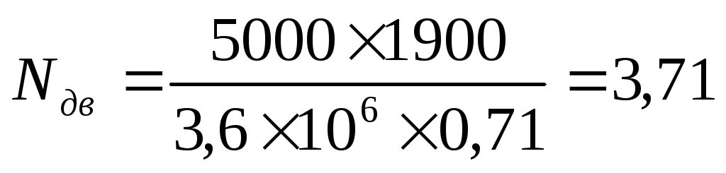 .
.
According to the received power and rotational speed, an electric motor is selected for the fan:
Motor type
Power N dv =
Speed n = 980 rpm.
Traction unit calculation
We accept brick for installation chimney height H tr = 30 m.
Flue gas flow at the chimney outlet
 , m 3 /s (70)
where V g is the total volume of gaseous combustion products V g = 13.381 m 3 /m 3.
Chimney mouth diameter
 ,m (71)
 ,
,
where Wout - the speed of movement of flue gases at the outlet of the chimney with artificial draft can reach 20 m / s. Taking into account the possibility of further expansion of the boiler house, we recommend taking the Wout value of about 15 m/s.


The resulting diameter is rounded up to the nearest recommended SNiP II-35-76.
We accept the diameter of the mouth of the chimney - 1.2 m.
In accordance with SNiP II-35-76, in order to prevent the penetration of flue gases into the structure of the walls of brick pipes, positive static pressure on the walls of the exhaust shaft is not allowed. To do this, you need to fulfill the condition R<10, где R - определяющий критерий
 (73)
(73)

Here  - coefficient of friction;
i - constant slope of the inner surface of the upper section of the pipe;
 - density of outside air at design mode, kg/m 3 ;
d in - diameter of the mouth of the chimney, m;
h o - dynamic gas pressure in the outlet of the chimney, Pa,
 , Pa (74)
 ,
,
where W out - gas velocity in the pipe outlet, m/s;
p g - density of flue gases in the design mode
 , kg/m 3 (75)
 ,
,
where  \u003d 1.34, kg / m 3.
If R>10, then the diameter of the chimney should be increased.
 Two heads and six legs; four walk, and two lie still
 Self-esteem - what is it: concept, structure, types and levels
 Cassandra's Path, or Pasta Adventures War on Earth and Underground