SA Oscillatory circuit. Oscillatory circuit
The main device that determines the operating frequency of any alternator is an oscillatory circuit. The oscillatory circuit (Fig. 1) consists of an inductor L(consider the ideal case when the coil has no ohmic resistance) and the capacitor C and is called closed. The characteristic of a coil is its inductance, it is denoted L and is measured in Henry (H), the capacitor is characterized by the capacitance C, which is measured in farads (F).
Let the capacitor be charged at the initial moment of time (Fig. 1) so that one of its plates has a charge + Q 0 , and on the other - charge - Q 0 . In this case, an electric field is formed between the plates of the capacitor, which has an energy
where is the amplitude (maximum) voltage or potential difference across the capacitor plates.
After the circuit is closed, the capacitor begins to discharge and an electric current will flow through the circuit (Fig. 2), the value of which increases from zero to the maximum value. Since an alternating current flows in the circuit, an EMF of self-induction is induced in the coil, which prevents the capacitor from discharging. Therefore, the process of discharging the capacitor does not occur instantly, but gradually. At each moment of time, the potential difference across the capacitor plates
(where is the charge of the capacitor at a given time) is equal to the potential difference across the coil, i.e. equal to self-induction emf
| Fig.1 | Fig.2 |
When the capacitor is completely discharged and , the current in the coil will reach its maximum value (Fig. 3). The induction of the magnetic field of the coil at this moment is also maximum, and the energy of the magnetic field will be equal to
Then the current strength begins to decrease, and the charge will accumulate on the capacitor plates (Fig. 4). When the current decreases to zero, the charge of the capacitor reaches its maximum value. Q 0 , but the plate, previously positively charged, will now be negatively charged (Fig. 5). Then the capacitor begins to discharge again, and the current in the circuit will flow in the opposite direction.
So the process of charge flowing from one plate of the capacitor to another through the inductor is repeated again and again. They say that in the circuit occur electromagnetic oscillations. This process is associated not only with fluctuations in the magnitude of the charge and voltage on the capacitor, the current strength in the coil, but also with the transfer of energy from the electric field to the magnetic field and vice versa.
| Fig.3 | Fig.4 |
Recharging the capacitor to the maximum voltage will occur only when there is no energy loss in the oscillatory circuit. Such a circuit is called ideal.
In real circuits, the following energy losses take place:
1) heat losses, because R ¹ 0;
2) losses in the capacitor dielectric;
3) hysteresis losses in the coil core;
4) radiation losses, etc. If we neglect these energy losses, then we can write that , i.e.
Oscillations occurring in an ideal oscillatory circuit in which this condition is satisfied are called free, or own, oscillations of the contour.
In this case, the voltage U(and charge Q) on the capacitor varies according to the harmonic law:
where n is the natural frequency of the oscillatory circuit, w 0 = 2pn is the natural (circular) frequency of the oscillatory circuit. The frequency of electromagnetic oscillations in the circuit is defined as
Period T- the time during which one complete oscillation of the voltage across the capacitor and the current in the circuit takes place, is determined Thomson's formula
The current strength in the circuit also changes according to the harmonic law, but lags behind the voltage in phase by . Therefore, the dependence of the current strength in the circuit on time will have the form
Figure 6 shows graphs of voltage changes U on the capacitor and current I in a coil for an ideal oscillatory circuit.
In a real circuit, the energy will decrease with each oscillation. The amplitudes of the voltage on the capacitor and the current in the circuit will decrease, such oscillations are called damped. They cannot be used in master generators, because the device will work at best in a pulsed mode.
| Fig.5 | Fig.6 |
To obtain undamped oscillations, it is necessary to compensate for energy losses at a wide variety of operating frequencies of devices, including those used in medicine.
"Damped oscillations" - 26.1. Free damped mechanical oscillations; 26.2. damping factor and logarithmic damping decrement; 26.26. Self-oscillations; Today: Saturday, August 6, 2011 Lecture 26. Fig. 26.1.
"Harmonic vibrations" - The beat method is used for tuning musical instruments, hearing analysis, etc. Figure 4. View fluctuations. (2.2.4). ?1 is the phase of the 1st oscillation. - The resulting oscillation, also harmonic, with a frequency?: Projection of circular motion on the y-axis, also makes a harmonic oscillation. Figure 3
"Frequency of oscillation" - Reflection of sound. Speed of sound in various media, m/s (at t = 20°C). Mechanical vibrations with a frequency of less than 20 Hz are called infrasound. Understand sound as a phenomenon. Project goals. Sound sources. The speed of sound depends on the properties of the medium in which the sound propagates. What determines the timbre of a sound?
"Mechanical vibrations and waves" - Properties of waves. Types of waves. Mathematical pendulum. The period of free oscillations of a mathematical pendulum. Energy transformation. Laws of reflection. Spring pendulum. The hearing organs are most sensitive to sounds with frequencies from 700 to 6000 Hz. Free Forced Self Oscillations.
"Mechanical vibrations" - Harmonic. Elastic waves are mechanical disturbances propagating in an elastic medium. Mathematical pendulum. Waves. Wavelength (?) is the distance between the nearest particles oscillating in the same phase. Forced. Forced vibrations. Graph of a mathematical pendulum. Waves - the propagation of vibrations in space over time.
"Mechanical resonance" - Amplitude of forced oscillations. State educational institution Gymnasium No. 363 of the Frunzensky district. The destructive role of resonance Bridges. Resonance in technology. Thomas Young. 1. Physical basis of resonance Forced vibrations. Mechanical reed frequency meter - a device for measuring the frequency of vibrations.
There are 10 presentations in total in the topic
Thomson formula:
The period of electromagnetic oscillations in an ideal oscillatory circuit (i.e., in such a circuit where there is no energy loss) depends on the inductance of the coil and the capacitance of the capacitor and is found according to the formula first obtained in 1853 by the English scientist William Thomson:
The frequency is related to the period by an inversely proportional dependence ν = 1/Т.
For practical application, it is important to obtain undamped electromagnetic oscillations, and for this it is necessary to replenish the oscillatory circuit with electricity in order to compensate for the losses.
To obtain undamped electromagnetic oscillations, a undamped oscillation generator is used, which is an example of a self-oscillating system.
See below "Forced Electrical Vibrations"
FREE ELECTROMAGNETIC OSCILLATIONS IN THE CIRCUIT
ENERGY CONVERSION IN AN OSCILLATING CIRCUIT
See above "Oscillation circuit"
NATURAL FREQUENCY IN THE LOOP
See above "Oscillation circuit"
FORCED ELECTRICAL OSCILLATIONS
ADD DIAGRAM EXAMPLES
If in a circuit that includes inductance L and capacitance C, the capacitor is somehow charged (for example, by briefly connecting a power source), then periodic damped oscillations will occur in it:
u = Umax sin(ω0t + φ) e-αt
ω0 = (Natural oscillation frequency of the circuit)
To ensure undamped oscillations, the generator must necessarily include an element capable of connecting the circuit to the power source in time - a key or an amplifier.
In order for this switch or amplifier to open only at the right moment, feedback from the circuit to the control input of the amplifier is necessary.
An LC-type sinusoidal voltage generator must have three main components:
resonant circuit
Amplifier or key (on a vacuum tube, transistor or other element)
Feedback
Consider the operation of such a generator.
If the capacitor C is charged and it is recharged through the inductance L in such a way that the current in the circuit flows counterclockwise, then e occurs in the winding that has an inductive connection with the circuit. d.s., blocking the transistor T. The circuit is disconnected from the power source.
In the next half-cycle, when the reverse charge of the capacitor occurs, an emf is induced in the coupling winding. of another sign and the transistor opens slightly, the current from the power source passes into the circuit, recharging the capacitor.
If the amount of energy supplied to the circuit is less than the losses in it, the process will begin to decay, although more slowly than in the absence of an amplifier.
With the same replenishment and energy consumption, the oscillations are undamped, and if the replenishment of the circuit exceeds the losses in it, then the oscillations become divergent.
The following method is usually used to create a undamped character of oscillations: at small amplitudes of oscillations in the circuit, such a collector current of the transistor is provided in which the replenishment of energy exceeds its consumption. As a result, the oscillation amplitudes increase and the collector current reaches the saturation current value. A further increase in the base current does not lead to an increase in the collector current, and therefore the increase in the oscillation amplitude stops.
AC ELECTRIC CURRENT
AC GENERATOR (ac.11 class. p.131)
EMF of a frame rotating in the field
Alternator.
In a conductor moving in a constant magnetic field, an electric field is generated, an EMF of induction occurs.
The main element of the generator is a frame rotating in a magnetic field by an external mechanical motor.
Let us find the EMF induced in a frame of size a x b, rotating with an angular frequency ω in a magnetic field with induction B.
Let the angle α between the magnetic induction vector B and the frame area vector S equal zero in the initial position. In this position, no charge separation occurs.
In the right half of the frame, the velocity vector is co-directed to the induction vector, and in the left half it is opposite to it. Therefore, the Lorentz force acting on the charges in the frame is zero
When the frame is rotated through an angle of 90o, the charges are separated in the sides of the frame under the action of the Lorentz force. In the sides of the frame 1 and 3, the same induction emf arises:
εi1 = εi3 = υBb
The separation of charges in sides 2 and 4 is insignificant, and therefore the induction emf arising in them can be neglected.
Taking into account the fact that υ = ω a/2, the total EMF induced in the frame:
εi = 2 εi1 = ωB∆S

The EMF induced in the frame can be found from Faraday's law of electromagnetic induction. The magnetic flux through the area of the rotating frame changes with time depending on the angle of rotation φ = wt between the lines of magnetic induction and the area vector.
When the loop rotates with a frequency n, the angle j changes according to the law j = 2πnt, and the expression for the flow takes the form:
Φ = BDS cos(wt) = BDS cos(2πnt)
According to Faraday's law, changes in the magnetic flux create an induction emf equal to minus the rate of flux change:
εi = - dΦ/dt = -Φ’ = BSω sin(ωt) = εmax sin(wt) .
where εmax = wBDS is the maximum EMF induced in the frame
Therefore, the change in the EMF of induction will occur according to a harmonic law.
If, with the help of slip rings and brushes sliding along them, we connect the ends of the coil with an electrical circuit, then under the action of the induction EMF, which changes over time according to a harmonic law, forced electrical oscillations of the current strength - alternating current - will occur in the electrical circuit.
In practice, a sinusoidal EMF is excited not by rotating a coil in a magnetic field, but by rotating a magnet or electromagnet (rotor) inside the stator - stationary windings wound on steel cores.
Go to page:
If we compare Fig. 50 with fig. 17, which shows the vibrations of a body on springs, it is not difficult to establish a great similarity in all stages of the process. It is possible to compile a kind of "dictionary", with the help of which the description of electrical vibrations can be immediately translated into a description of mechanical ones, and vice versa. Here is the dictionary.
Try to reread the previous paragraph with this "dictionary". At the initial moment, the capacitor is charged (the body is deflected), i.e., a supply of electrical (potential) energy is reported to the system. The current begins to flow (the body gains speed), after a quarter of the period the current and magnetic energy are the largest, and the capacitor is discharged, the charge on it is zero (the body's speed and its kinetic energy are the largest, and the body passes through the equilibrium position), etc.
Note that the initial charge of the capacitor, and hence the voltage across it, is created by the electromotive force of the battery. On the other hand, the initial deflection of the body is created by an externally applied force. Thus, the force acting on a mechanical oscillatory system plays a role similar to the electromotive force acting on an electrical oscillatory system. Our "dictionary" can therefore be supplemented by another "translation":
7) force, 7) electromotive force.
The similarity of the regularities of both processes goes further. Mechanical oscillations are attenuated due to friction: with each oscillation, part of the energy is converted into heat due to friction, so the amplitude becomes smaller and smaller. In the same way, with each recharge of the capacitor, part of the energy of the current is converted into heat, released due to the presence of resistance at the wire of the coil. Therefore, the electrical oscillations in the circuit are also damped. Resistance plays the same role for electrical vibrations as friction plays for mechanical vibrations.
In 1853 English physicist William Thomson (Lord Kelvin, 1824-1907) showed theoretically that natural electrical oscillations in a circuit consisting of a capacitance capacitor and an inductor are harmonic, and their period is expressed by the formula
(- in henry, - in farads, - in seconds). This simple and very important formula is called the Thomson formula. The oscillatory circuits themselves with capacitance and inductance are often also called Thomson, since Thomson was the first to give a theory of electrical oscillations in such circuits. Recently, the term “-contour” is increasingly used (and similarly “-contour”, “-contour”, etc.).
Comparing Thomson's formula with the formula that determines the period of harmonic oscillations of an elastic pendulum (§ 9), we see that the mass of the body plays the same role as inductance, and the stiffness of the spring plays the same role as the reciprocal of capacitance (). In accordance with this, in our "dictionary" the second line can be written like this:
2) the stiffness of the spring 2) the reciprocal of the capacitance of the capacitor.
By choosing different and , you can get any periods of electrical oscillations. Naturally, depending on the period of electrical oscillations, it is necessary to use various methods for their observation and recording (oscillography). If we take, for example, and , then the period will be
i.e., oscillations will occur with a frequency of about . This is an example of electrical vibrations whose frequency lies in the audio range. Such fluctuations can be heard using a telephone and recorded on a loop oscilloscope. An electronic oscilloscope makes it possible to obtain a sweep of both these and higher-frequency oscillations. Radio engineering uses extremely fast oscillations - with frequencies of many millions of hertz. An electronic oscilloscope makes it possible to observe their shape just as well as we can see the shape of a pendulum with the help of a pendulum trace on a sooty plate (§ 3). Oscillography of free electrical oscillations with a single excitation of the oscillatory circuit is usually not used. The fact is that the state of equilibrium in the circuit is established in just a few periods, or, at best, in several tens of periods (depending on the relationship between the inductance of the circuit, its capacitance and resistance). If, say, the decay process practically ends in 20 periods, then in the above example of a circuit with periods of the entire flash of free oscillations, it will take only everything and it will be very difficult to follow the oscillogram with a simple visual observation. The problem is easily solved if the whole process - from the excitation of oscillations to their almost complete extinction - is periodically repeated. By making the scanning voltage of the electronic oscilloscope also periodic and synchronous with the process of excitation of oscillations, we will force the electron beam to “draw” the same oscillogram many times in the same place on the screen. With sufficiently frequent repetition, the picture observed on the screen will generally appear to be continuous, i.e., we will sit on a motionless and unchanging curve, an idea of which is given by Fig. 49b.
In the switch circuit shown in Fig. 49, a, a multiple repetition of the process can be obtained simply by periodically tossing the switch from one position to another.
Radio engineering has for the same much more advanced and faster electrical switching methods using electronic tube circuits. But even before the invention of electronic tubes, an ingenious method was invented for periodically repeating the excitation of damped oscillations in a circuit, based on the use of a spark charge. In view of the simplicity and clarity of this method, we will dwell on it in somewhat more detail.

Rice. 51. Scheme of spark excitation of oscillations in the circuit
The oscillatory circuit is broken by a small gap (spark gap 1), the ends of which are connected to the secondary winding of step-up transformer 2 (Fig. 51). The current from the transformer charges the capacitor 3 until the voltage across the spark gap becomes equal to the breakdown voltage (see Volume II, §93). At this moment, a spark discharge occurs in the spark gap, which closes the circuit, since the column of highly ionized gas in the spark channel conducts current almost as well as metal. In such a closed circuit, electrical oscillations will occur, as described above. As long as the spark gap conducts current well, the secondary winding of the transformer is practically short-circuited by the spark, so that the entire voltage of the transformer drops on its secondary winding, the resistance of which is much greater than the resistance of the spark. Consequently, with a well-conducting spark gap, the transformer delivers practically no energy to the circuit. Due to the fact that the circuit has resistance, part of the vibrational energy is spent on Joule heat, as well as on the processes in the spark, the oscillations damp out and after a short time the amplitudes of the current and voltage drop so much that the spark goes out. Then the electrical oscillations are interrupted. From this point on, the transformer charges the capacitor again until a breakdown occurs again, and the whole process is repeated (Fig. 52). Thus, the formation of a spark and its extinction play the role of an automatic switch that ensures the repetition of the oscillatory process.

Rice. 52. Curve a) shows how the high voltage changes on the open secondary winding of the transformer. At those moments when this voltage reaches the breakdown voltage, a spark jumps in the spark gap, the circuit closes, a flash of damped oscillations is obtained - curves b)
Lesson No. 48-169 Oscillatory circuit. Free electromagnetic oscillations. Energy conversion in an oscillatory circuit. Thompson formula.fluctuations- movements or states that repeat in time.Electromagnetic vibrations -These are vibrations of electrical andmagnetic fields that resistdriven by periodic changecharge, current and voltage. An oscillatory circuit is a system consisting of an inductor and a capacitor(Fig. a). If the capacitor is charged and closed to the coil, then current will flow through the coil (Fig. b). When the capacitor is discharged, the current in the circuit will not stop due to self-induction in the coil. The induction current, in accordance with the Lenz rule, will flow in the same direction and recharge the capacitor (Fig. c). The current in this direction will stop, and the process will repeat in the opposite direction (Fig. G).
Thus, in hesitationcircuitdyat electromagnetic oscillationsdue to the conversion of energyelectric field of the condensatera( W e =  )
into the energy of the magnetic field of the coil with current(W M =
)
into the energy of the magnetic field of the coil with current(W M =  ),
and vice versa.
),
and vice versa.
Harmonic oscillations are periodic changes in a physical quantity depending on time, occurring according to the law of sine or cosine.
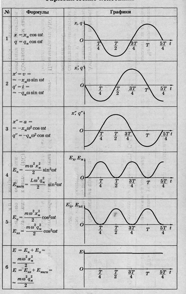 The equation describing free electromagnetic oscillations takes the form
q "= - ω 0 2 q (q" is the second derivative.
The main characteristics of the oscillatory motion:
The oscillation period is the minimum period of time T, after which the process is completely repeated.
The amplitude of harmonic oscillations is the module of the largest value of the oscillating quantity.
Knowing the period, you can determine the frequency of oscillations, that is, the number of oscillations per unit of time, for example, per second. If one oscillation occurs in time T, then the number of oscillations in 1 s ν is determined as follows: ν = 1/T.
Recall that in the International System of Units (SI), the oscillation frequency is equal to one if one oscillation occurs in 1 s. The unit of frequency is called the hertz (abbreviated as Hz) after the German physicist Heinrich Hertz.
After a period of time equal to the period T, i.e., as the cosine argument increases by ω 0
T, the value of the charge is repeated and the cosine takes the same value. From the course of mathematics it is known that the smallest period of the cosine is 2n. Therefore, ω 0
T=2π, whence ω 0
=  =2πν Thus, the quantity ω 0
- this is the number of oscillations, but not for 1 s, but for 2n s. It is called cyclical or circular frequency.
=2πν Thus, the quantity ω 0
- this is the number of oscillations, but not for 1 s, but for 2n s. It is called cyclical or circular frequency.
The frequency of free vibrations is called natural frequency of the vibrationalsystems. Often in what follows, for brevity, we will refer to the cyclic frequency simply as the frequency. Distinguish the cyclic frequency ω 0 on the frequency ν is possible by notation.
By analogy with the solution of a differential equation for a mechanical oscillatory system cyclic frequency of free electricfluctuations is: ω 0 = 
The period of free oscillations in the circuit is equal to: T=  =2π
=2π  - Thomson formula.
The phase of oscillations (from the Greek word phasis - the appearance, stage of development of a phenomenon) is the value of φ, which is under the sign of cosine or sine. The phase is expressed in angular units - radians. The phase determines the state of the oscillatory system at a given amplitude at any time.
Oscillations with the same amplitudes and frequencies may differ from each other in phases.
Since ω 0
= , then φ= ω 0
T=2π . The ratio shows what part of the period has passed from the moment the oscillations began. Any value of time expressed in fractions of a period corresponds to a phase value expressed in radians. So, after time t=
  (quarter period) φ=
  , after half the period φ \u003d π, after the whole period φ \u003d 2π, etc. You can plot the dependence
 charge not from time, but from phase. The figure shows the same cosine wave as the previous one, but plotted on the horizontal axis instead of time
different phase values φ.
Correspondence between mechanical and electrical quantities in oscillatory processes
Mechanical quantities
Tasks.942(932). The initial charge reported to the capacitor of the oscillatory circuit was reduced by 2 times. How many times have changed: a) voltage amplitude; b) current amplitude;
c) the total energy of the electric field of the capacitor and the magnetic field of the coil?
943(933). With an increase in the voltage on the capacitor of the oscillatory circuit by 20 V, the amplitude of the current strength increased by 2 times. Find the initial stress.
945(935). The oscillatory circuit consists of a capacitor with a capacity of C = 400 pF and an inductance coil L = 10 mH. Find the amplitude of current oscillations I t , if the amplitude of voltage fluctuations U t = 500 V.
952(942). After what time (in fractions of the period t / T) on the capacitor of the oscillatory circuit for the first time will there be a charge equal to half the amplitude value?
957(947). What inductance coil should be included in the oscillatory circuit in order to obtain a free oscillation frequency of 10 MHz with a capacitor capacitance of 50 pF?
Oscillatory circuit. The period of free oscillations.
1. After the capacitor of the oscillatory circuit was charged q \u003d 10 -5 C, damped oscillations appeared in the circuit. How much heat will be released in the circuit by the time the oscillations in it are completely damped? Capacitor capacitance C \u003d 0.01 μF.
2. The oscillatory circuit consists of a 400nF capacitor and a 9µH inductor. What is the natural oscillation period of the circuit?
3. What inductance should be included in the oscillatory circuit in order to obtain a natural oscillation period of 2∙ 10 -6 s with a capacitance of 100pF.
4. Compare spring rates k1/k2 of two pendulums with weights of 200g and 400g, respectively, if the periods of their oscillations are equal.
5. Under the action of a motionlessly hanging load on the spring, its elongation was 6.4 cm. Then the load was pulled and released, as a result of which it began to oscillate. Determine the period of these oscillations.
6. A load was suspended from the spring, it was taken out of equilibrium and released. The load began to oscillate with a period of 0.5 s. Determine the elongation of the spring after the oscillation stops. The mass of the spring is ignored.
7. For the same time, one mathematical pendulum makes 25 oscillations, and the other 15. Find their lengths if one of them is 10 cm shorter than the other.8. The oscillatory circuit consists of a 10mF capacitor and a 100mH inductor. Find the amplitude of voltage fluctuations if the amplitude of current fluctuations is 0.1A9. The inductance of the coil of the oscillatory circuit is 0.5mH. It is required to tune this circuit to a frequency of 1 MHz. What should be the capacitance of the capacitor in this circuit?Exam questions:
1. Which of the following expressions determines the period of free oscillations in an oscillatory circuit? BUT.; B.  ; AT.
; AT.  ; G.
; G.  ; D. 2.
2 . Which of the following expressions determines the cyclic frequency of free oscillations in an oscillatory circuit? A. B.
  AT.
AT.  G.
G.  D. 2π
D. 2π
3. The figure shows a graph of the dependence of the X coordinate of a body performing harmonic oscillations along the x axis on time. What is the period of oscillation of the body?
A. 1 s; B. 2 s; B. 3 s . D. 4 p.
4. The figure shows the wave profile at a certain point in time. What is its length?
A. 0.1 m. B. 0.2 m. C. 2 m. D. 4 m. D. 5 m.5
 . The figure shows a graph of the dependence of the current through the coil of the oscillatory circuit on time. What is the period of current oscillation? A. 0.4 s. B. 0.3 s. B. 0.2 s. D. 0.1 s.
 E. Among the answers A-D, there is no correct one.

6. The figure shows the wave profile at a certain point in time. What is its length?
A. 0.2 m. B. 0.4 m. C. 4 m. D. 8 m. D. 12 m.
7. Electric oscillations in the oscillatory circuit are given by the equation q \u003d 10 -2 ∙ cos 20t (C).
What is the amplitude of charge oscillations?
BUT . 10 -2 Cl. B.cos 20t Cl. B.20t Cl. D.20 Cl. E. Among the answers A-D, there is no correct one.
8. With harmonic oscillations along the OX axis, the coordinate of the body changes according to the law X=0.2cos(5t+  ). What is the amplitude of the body's vibrations?
A. Xm; B. 0.2 m; C. cos(5t+) m; (5t+)m; D.m
9. Oscillation frequency of the wave source 0.2 s -1 wave propagation speed 10 m/s. What is the wavelength? A. 0.02 m. B. 2 m. C. 50 m.
D. According to the condition of the problem, it is impossible to determine the wavelength. E. Among the answers A-D, there is no correct one.
10. Wavelength 40 m, propagation speed 20 m/s. What is the oscillation frequency of the wave source?
A. 0.5 s -1 . B. 2 s -1 . V. 800 s -1 .
D. According to the condition of the problem, it is impossible to determine the oscillation frequency of the wave source.
E. Among the answers A-D, there is no correct one.
3
 Two heads and six legs; four walk, and two lie still
 Self-esteem - what is it: concept, structure, types and levels
 Cassandra's Path, or Pasta Adventures War on Earth and Underground